

Grouping system
- Summary
- Abstract
- Description
- Claims
- Application Information
AI Technical Summary
Benefits of technology
Problems solved by technology
Method used
Image

Examples
first exemplary embodiment
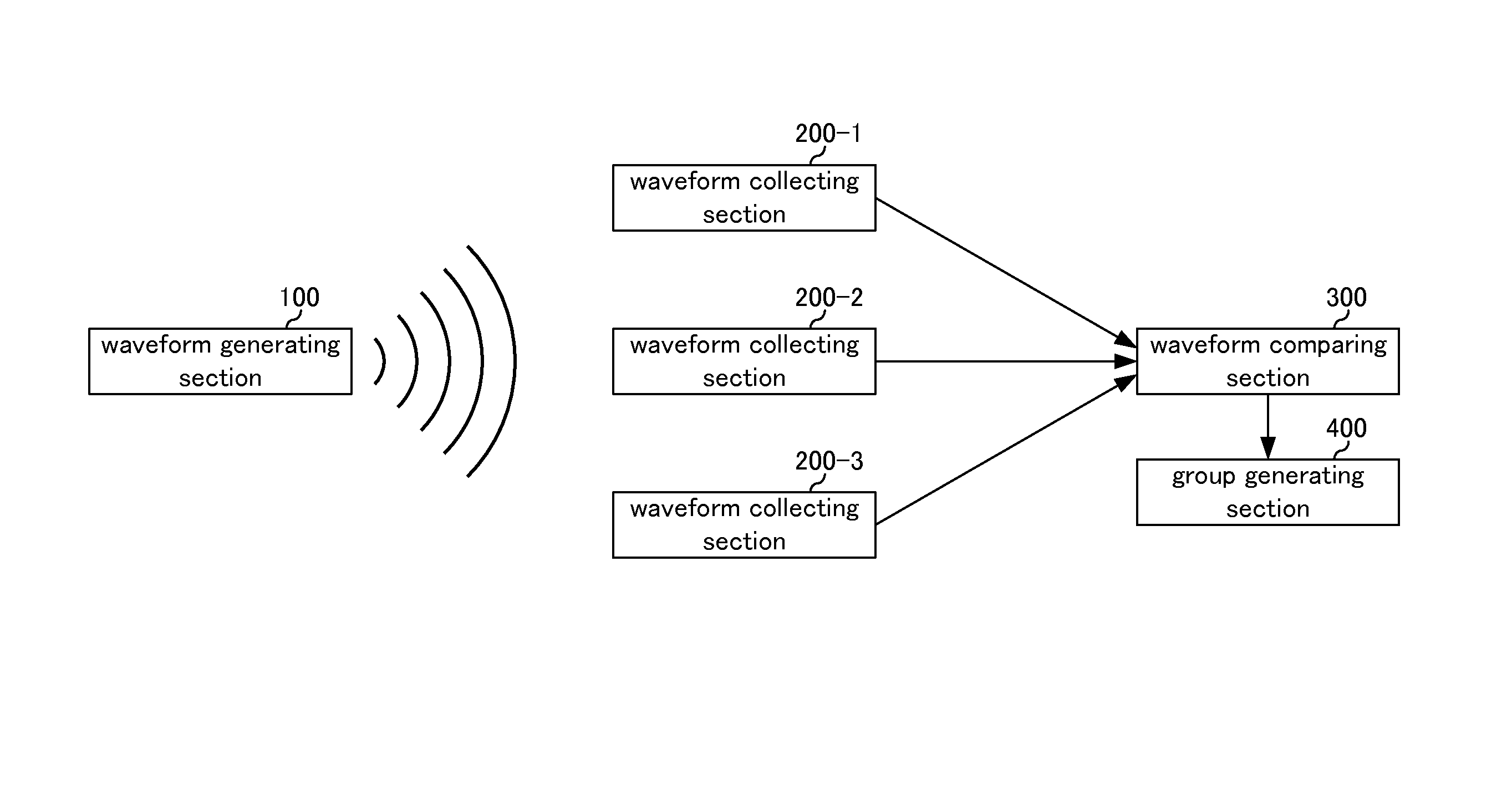
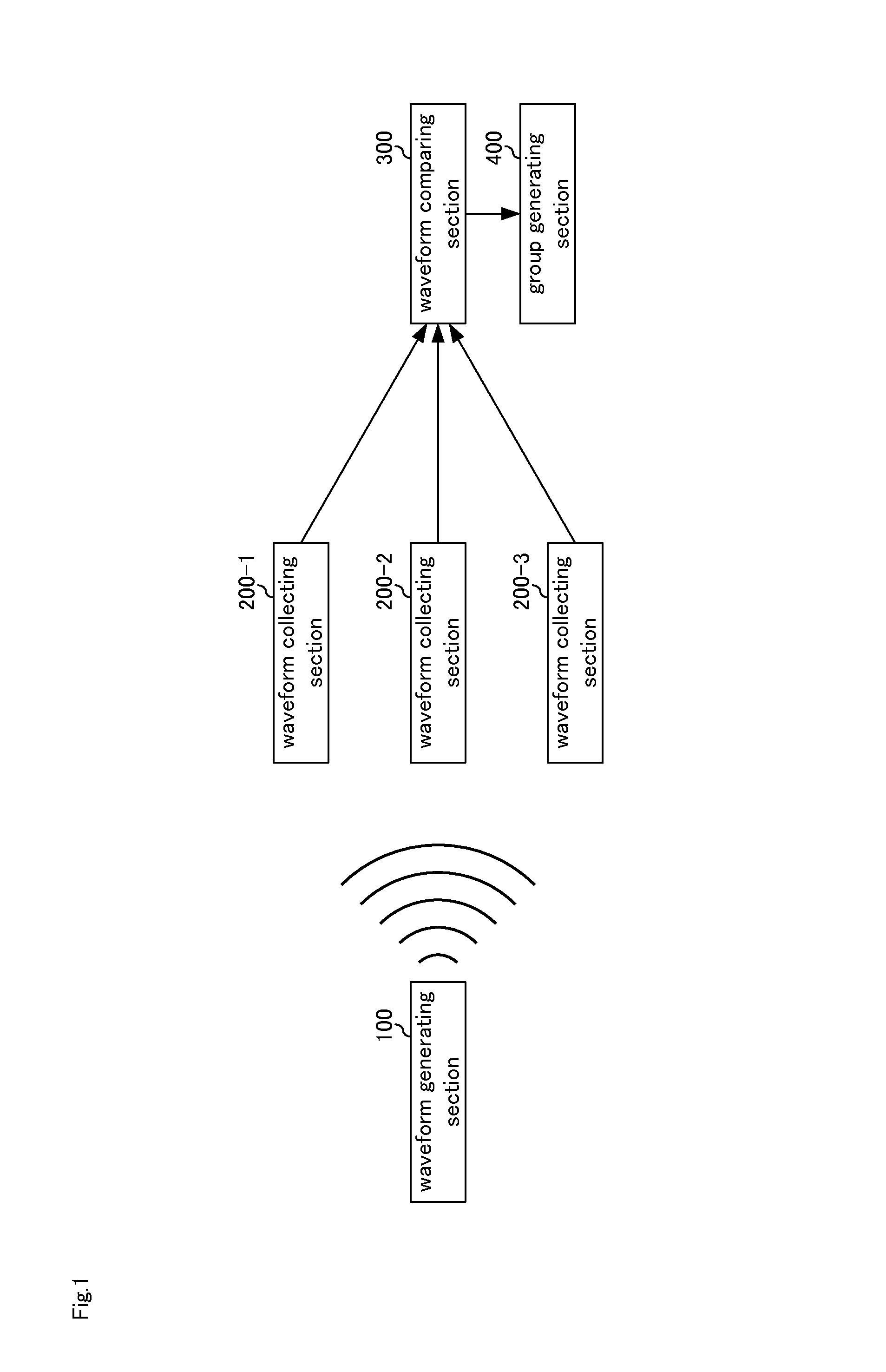
[0056]FIG. 1 shows a first exemplary embodiment of a grouping system including waveform generating section 100, waveform collecting sections 200-1 to 200-3, waveform comparing section 300, and group generating section 400. Although the example shown in FIG. 1 includes three waveform collecting sections, the number of the waveform collecting sections may be any number without being limited to three.
[0057]Waveform generating section 100 generates a specified waveform and outputs it by using a speaker, a vibrator and the like. The waveform is not limited to those that can be sensed by a human being such as acoustic waves and oscillatory waves but may be a waveform that cannot be sensed by a human being. For example, the waveform may be a supersonic wave which in an inaudible band of 17000 Hz or more and 20 Hz or less and whose waveform or oscillation cannot be sensed, as long as it is detectable by waveform collecting sections 200-1 to 200-3. For example, when the waveform is sound, it...
second exemplary embodiment
[0112]Although the case of one waveform generating section 100 is shown in the first exemplary embodiment, waveform generating sections may also be provided.
[0113]FIG. 7 shows a second exemplary embodiment of the grouping system including waveform generating sections 100-1 to 100-3, waveform collecting sections 200-1 to 200-3, waveform comparing section 300, and group generating section 400. Although the example shown in FIG. 7 includes three waveform generating sections and waveform collecting sections, the number of the waveform generating sections and the waveform collecting sections may be any number without being limited to three.
[0114]Waveform generating sections 100-1 to 100-3 include the same functions as waveform generating section 100 shown in FIG. 1.
[0115]Other component members shown in FIG. 7 include the same functions as those shown in FIG. 1.
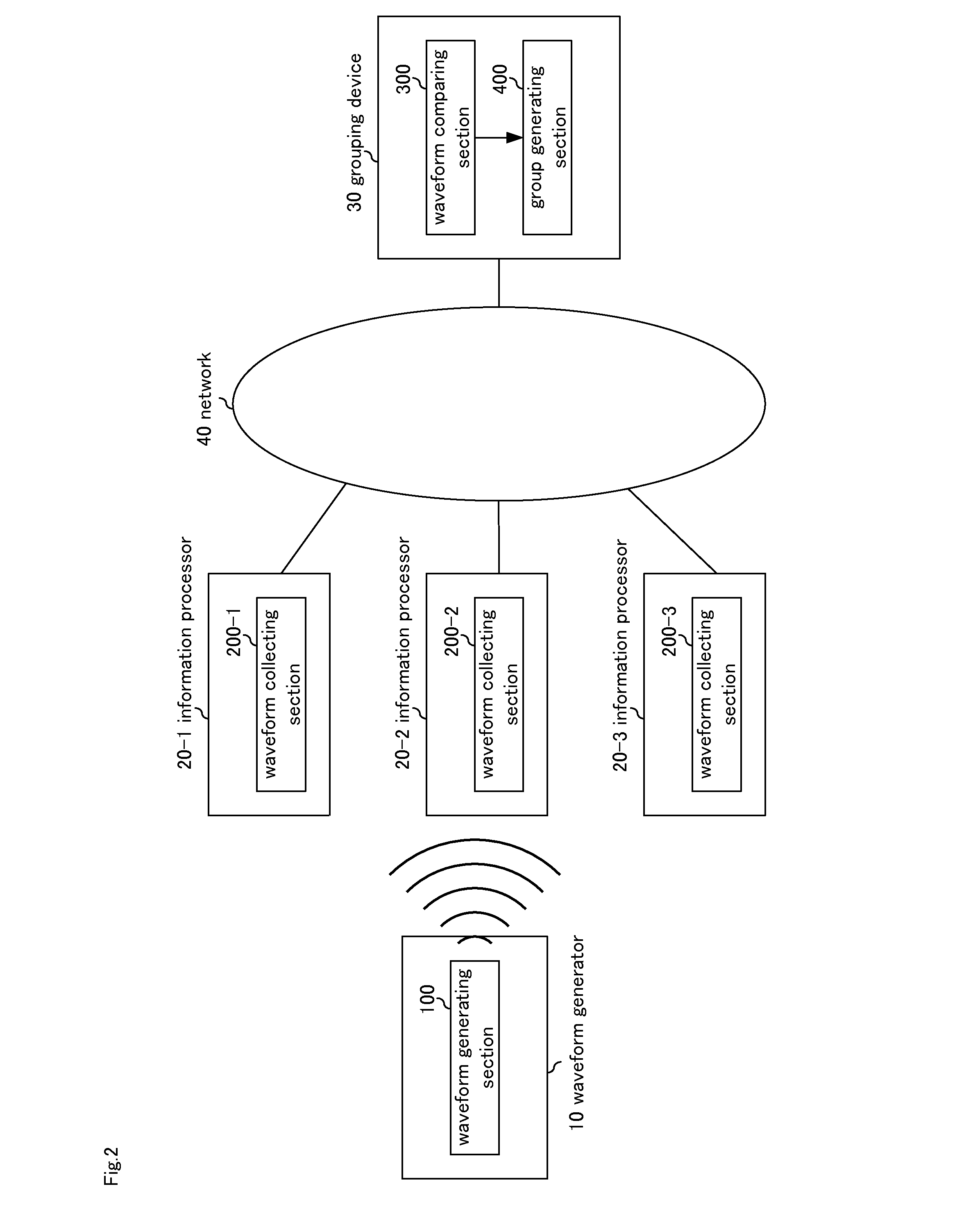
[0116]These component members are placed in the waveform generator, the information processor and the grouping device as in the ...
third exemplary embodiment
[0117]Waveforms generated by the waveform generating section may be recognized in advance in the waveform comparing section.
[0118]FIG. 8 shows a third exemplary embodiment of the grouping system including waveform generating section 100, waveform collecting sections 200-1 to 200-3, waveform comparing section 300, group generating section 400, and waveform control section 500. Although the example shown in FIG. 8 includes three waveform collecting sections, the number of the waveform collecting sections may be any number without being limited to three.
[0119]Waveform control section 500 controls waveform generating section 100 and waveform comparing section 300. More specifically, waveform control section 500 controls waveform generation in waveform generating section 100 (such as timing of generating a waveform), and reports a control detail as waveform information to waveform comparing section 300. Waveform control section 500 also changes waveforms to be generated by waveform gener...
PUM
 Abstract
Description
Claims
Application Information