
Wireless communication system and wireless communication apparatus and control method thereof

a wireless communication and wireless communication technology, applied in the direction of wireless communication services, broadcast service distribution, network topologies, etc., can solve the problems of radio interference between neighboring groups, cumbersome and complicated manner of operation for dynamically dividing students according to a subject and time, and significant degraded response tim

Active Publication Date: 2009-04-23
CANON KK
View PDF6 Cites 8 Cited by
  • Summary
  • Abstract
  • Description
  • Claims
  • Application Information

AI Technical Summary

Benefits of technology

The present invention aims to solve problems in existing wireless communication systems by facilitating the grouping of wireless communication terminal stations and preventing communication interference between groups. This is achieved through a wireless communication system that includes a plurality of wireless communication apparatuses and a first access point apparatus of a first group. The system also includes a unit to activate a second wireless communication apparatus as a second access point apparatus of a second group and a transmission power control unit to control the transmission power of the second access point apparatus and the multiple wireless communication apparatuses in the second group after the second group is established. The technical effects of this invention include improved wireless communication network efficiency, reduced interference between groups, and improved overall network performance.

Problems solved by technology

(1) If many students access the teacher at a time in order to ask questions without arbitration, contention for a radio band occurs, which significantly degrades the response time.
(2) The manner of operation for dynamically dividing students into arbitrary groups according to a subject and time is cumbersome and complicated.
(3) Once students are divided into groups, the groups use their individual wireless channels. Therefore, radio interference occurs between neighboring groups.

Method used


Image

  • Wireless communication system and wireless communication apparatus and control method thereof
  • Wireless communication system and wireless communication apparatus and control method thereof
  • Wireless communication system and wireless communication apparatus and control method thereof

Examples


first exemplary embodiment

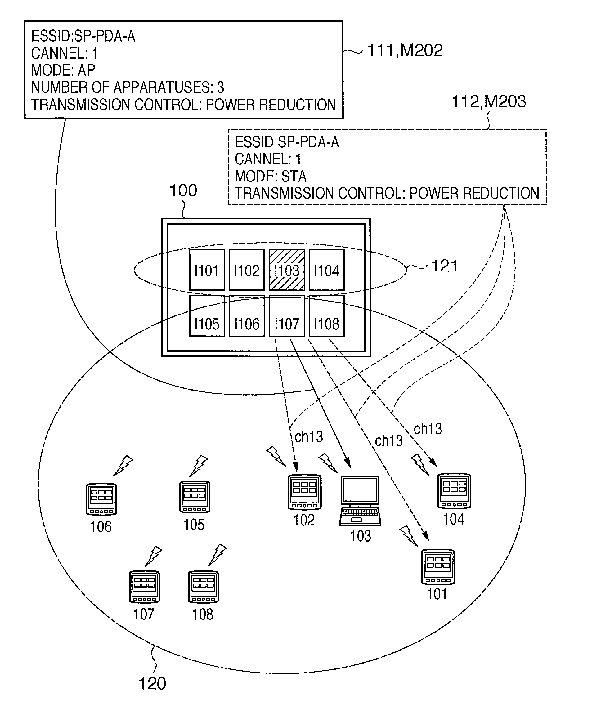
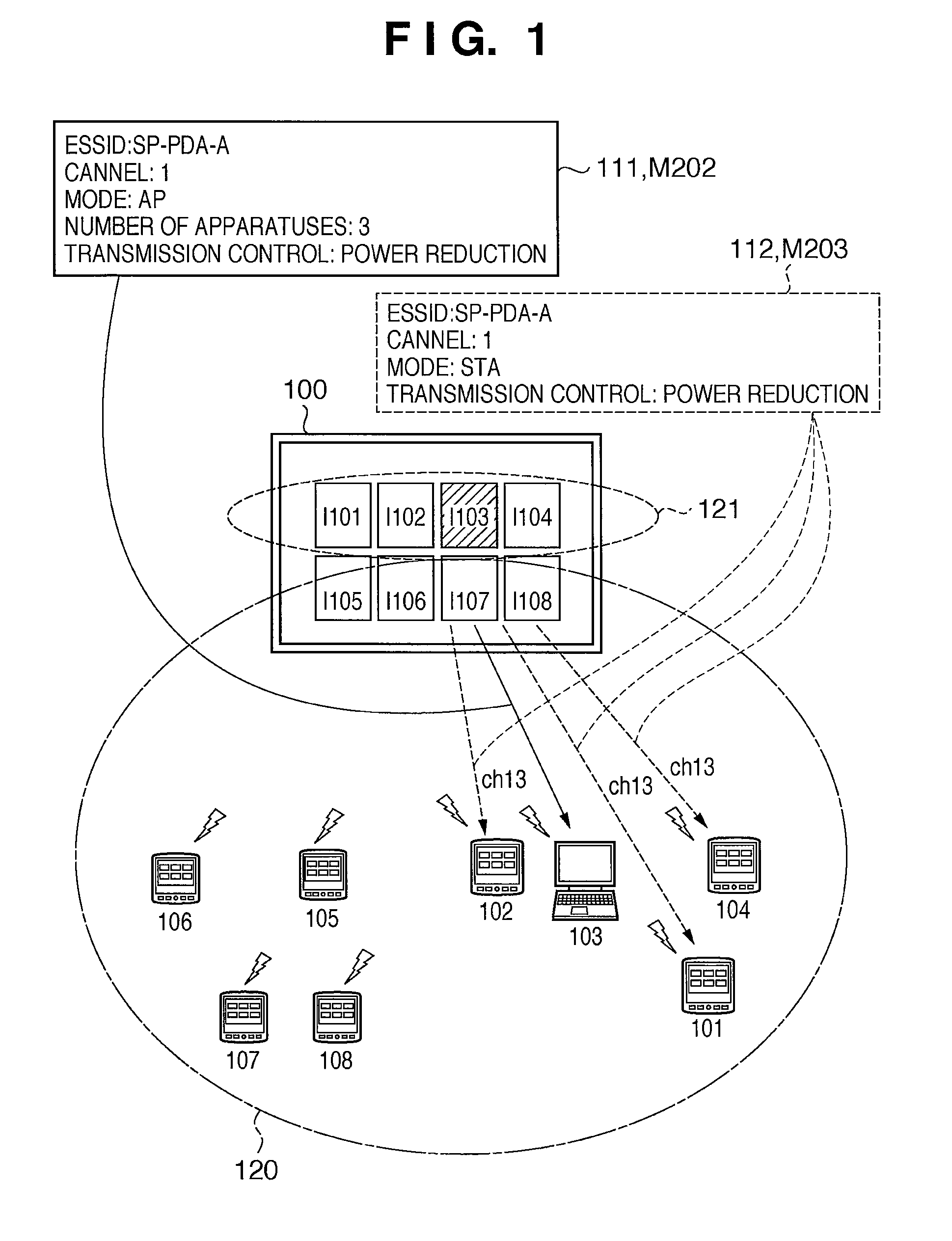
[0050]The wireless communication system according to the first exemplary embodiment of the present invention will be described with reference to FIGS. 1 to 4 and 8.

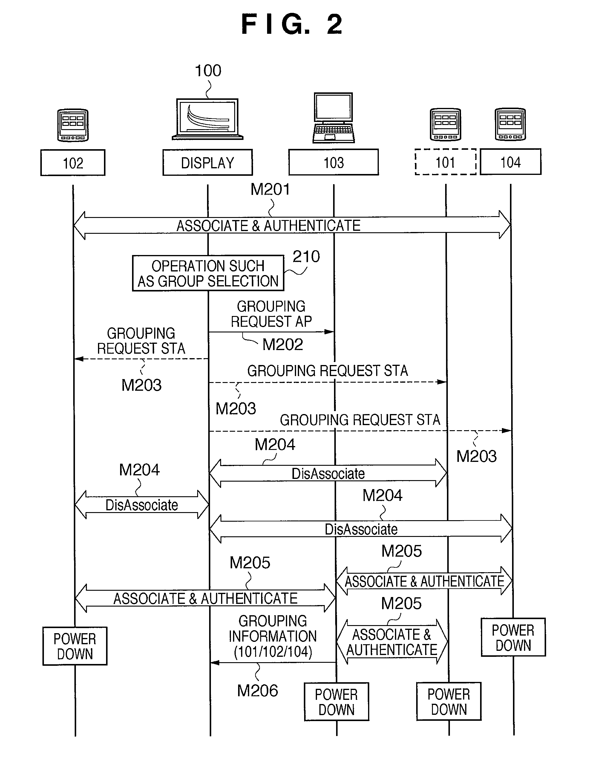
[0051]FIG. 4 is a flowchart explaining a control process performed by a wireless communication apparatus 101 to 108 according to the first exemplary embodiment. A program performing the process has been installed on the HDD 1804. When the program is to be executed, the program is loaded into the RAM 1802 and executed under the control of the CPU 1801. FIG. 8 shows a network configuration of the wireless communication system after grouping according to the first exemplary embodiment. The first exemplary embodiment of the present invention will be described with reference to these figures as appropriate.

[0052]In FIG. 1, the wireless communication apparatuses 101 to 108 operating in the STA mode have been associated and authenticated with the display apparatus 100, which has an AP function for wireless LAN (M201 in FIG. 2). ...

second exemplary embodiment

[0076]A second exemplary embodiment of the present invention will be described. A configuration and a control procedure of a wireless communication system according to the second exemplary embodiment will be described with reference to FIGS. 1, 3, 5, 6, 7 and 8. The wireless communication apparatuses and display apparatus according to the second exemplary embodiment have hardware configurations similar to that in the first exemplary embodiment and therefore the description of which will be omitted.

[0077]FIG. 5 is a sequence chart illustrating a process of sending and receiving messages among a display apparatus and wireless communication apparatuses constituting a wireless communication system according to the second exemplary embodiment of the present invention. The same elements in FIG. 5 as those in FIG. 2 are indicated by the same reference numerals and symbols.

[0078]FIG. 6 is a flowchart explaining a control process performed by the display apparatus 100 of the wireless communi...

third exemplary embodiment

[0108]A control procedure by a wireless communication system according to a third exemplary embodiment of the present invention will be described with reference to FIGS. 9 to 11. The hardware configuration of wireless communication apparatus and a display apparatus according to the third exemplary embodiment is the same as that in the first exemplary embodiment described above and therefore the description of which will be omitted.

[0109]FIG. 9 depicts a view illustrating an example of a network configuration of the wireless communication system according to the third exemplary embodiment of the present invention.

[0110]Reference numeral 1400 denotes a group of icons of wireless communication terminals selected in grouping. Reference numeral 1401 denotes a message to a wireless communication apparatus to be activated in the AP mode. Reference numeral 1402 denotes messages to wireless communication apparatuses to be activated in the STA mode.

[0111]In FIG. 9, the control area 302 formed...


PUM


Abstract

A display apparatus selects one of multiple wireless communication apparatuses and activates the selected wireless communication apparatus as a second access point of a second group. The activated wireless communication apparatus establishes the second group including multiple wireless communication apparatuses. After the second group is thus established, the transmission power of the wireless communication apparatus activated as the access point and the multiple wireless communication apparatuses included in the second group is controlled.

Description

BACKGROUND OF THE INVENTION[0001]1. Field of the Invention[0002]The present invention relates to a wireless communication system and a wireless communication apparatus that establishes a wireless communication network with other wireless communication apparatuses through a wireless access point apparatus, and a control method for controlling the wireless communication apparatus.[0003]2. Description of the Related Art[0004]Products conforming to IEEE 802.11 standards, which are standards for wireless local area networks, are widely used in these years. Configurations of wireless LANs are broadly classified into infrastructure mode and ad hoc mode. An infrastructure mode network includes multiple stations (STAs, terminal stations) and access points (AP, base stations). An ad-hoc mode network includes multiple STAs, and wireless communication apparatuses directly communicate with each other without using an access point.[0005]Educational institutions such as schools and cram schools ar...

Claims


Application Information

Patent Timeline
Patent Type & Authority Applications(United States)
IPC IPC(8): H04W84/12
CPCH04W4/08H04W8/186H04W52/245H04W88/08H04W88/02H04W88/06H04W84/20
Inventor IKEDA, NOBUHIRO
Owner CANON KK
Learn More