
System and method for operating a wind turbine

a technology for wind turbines and systems, applied in the field of wind turbines, can solve the problems of significantly increasing the cost of replacement of components, component wear at a rate different than the anticipated rate, and the overall operating life may be limited, so as to reduce the number of component cycles per unit of time, minimize premature maintenance operations, and maximize the effect of maintenance performed

Active Publication Date: 2022-05-24
GENERAL ELECTRIC CO
View PDF22 Cites 1 Cited by
  • Summary
  • Abstract
  • Description
  • Claims
  • Application Information

AI Technical Summary

Benefits of technology

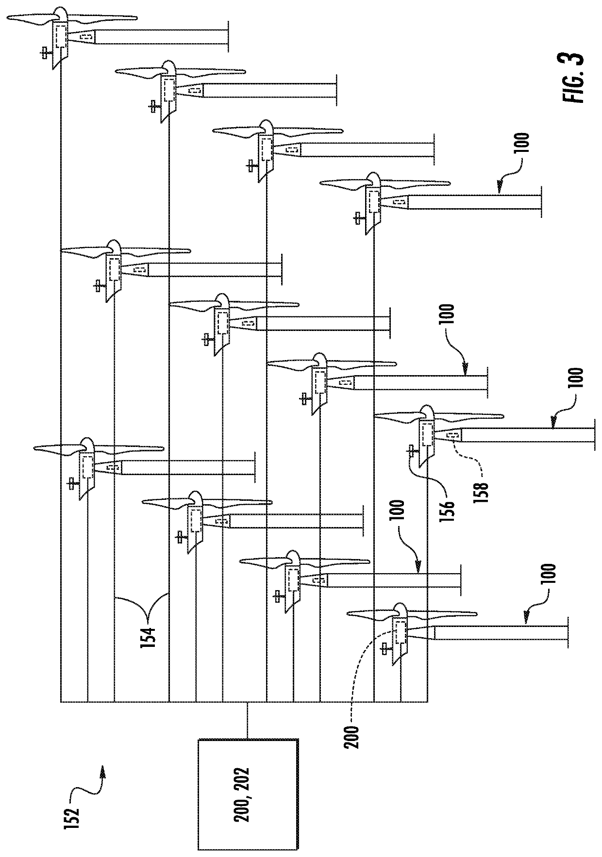
This patent describes a method for maintenance and repair of wind turbines in a wind farm. The method involves grouping together wind turbines with similar maintenance needs, and creating a maintenance schedule to minimize premature repairs and maximize efficiency during maintenance operations. The method also includes redistributing power generation requirements from one wind turbine to another to reduce wear and tear on components. Additionally, the method suggests alternating periods of idling with periods of active power production to further delay the approach to the shutdown threshold, which makes it easier to prioritize repairs and reduce downtime for wind turbines. Overall, this method aims to optimize maintenance and repair of wind turbines in a wind farm to improve overall efficiency and prolong the lifespan of wind turbines.

Problems solved by technology

In many instances, this anticipated overall operating life may be limited based on the anticipated fatigue life of one or more of the wind turbine components.
Further, the operational employment of the components may result in the component wearing at a rate different than the anticipated rate.
Because component failure may occur at any time, service actions and parts planning are typically based on prior knowledge and past field observations, rather than on quantifiable prognostics.
This may result in a significantly increased cost due to changing out components when a service action is not warranted by the wear of the component.
This may result in an unexpected failure of the component and a resultant shutdown of the wind turbine.
Because the shutdown may be unexpected, it may be an extended shutdown due to replacement part availability or it may be necessary to maintain an excessive number of parts in inventory.
Additionally, unanticipated failures of components may result in inefficient service actions at the wind farm, such as multiple visits from a ground crane, resulting in increased costs.

Method used


Image

  • System and method for operating a wind turbine
  • System and method for operating a wind turbine
  • System and method for operating a wind turbine

Examples


Embodiment Construction

[0035]Reference now will be made in detail to embodiments of the invention, one or more examples of which are illustrated in the drawings. Each example is provided by way of explanation of the invention, not limitation of the invention. In fact, it will be apparent to those skilled in the art that various modifications and variations can be made in the present invention without departing from the scope or spirit of the invention. For instance, features illustrated or described as part of one embodiment can be used with another embodiment to yield a still further embodiment. Thus, it is intended that the present invention covers such modifications and variations as come within the scope of the appended claims and their equivalents.

[0036]As used herein, the terms “first”, “second”, and “third” may be used interchangeably to distinguish one component from another and are not intended to signify location or importance of the individual components.

[0037]The terms “coupled,”“attached to,”...


PUM


Abstract

A system and method are provided for operating and maintaining a wind turbine. Accordingly, a plurality of data inputs are received. The plurality of data inputs represent a plurality of monitored attributes of a component of the wind turbine. A consolidated risk index for the component is determined using the plurality of monitored attributes, and a range of potential risk indices is forecasted. A remaining-useful-life distribution is determined based on the damage potential and an end-of-life damage threshold. The wind turbine is shut down or idled if the remaining-useful-life distribution is below a shutdown threshold.

Description

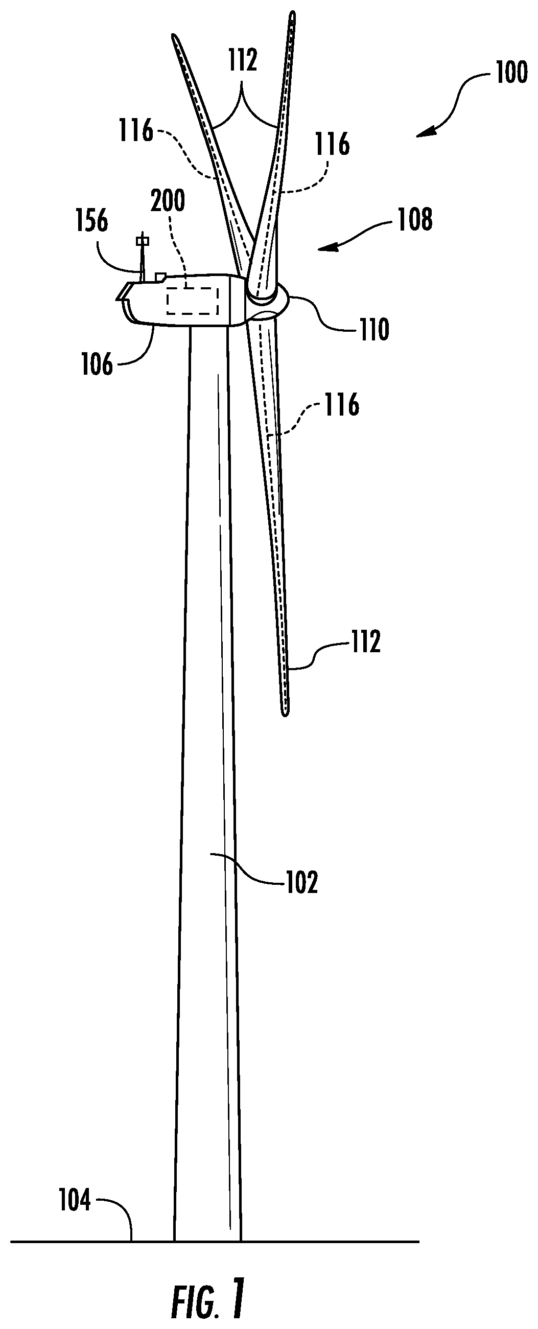
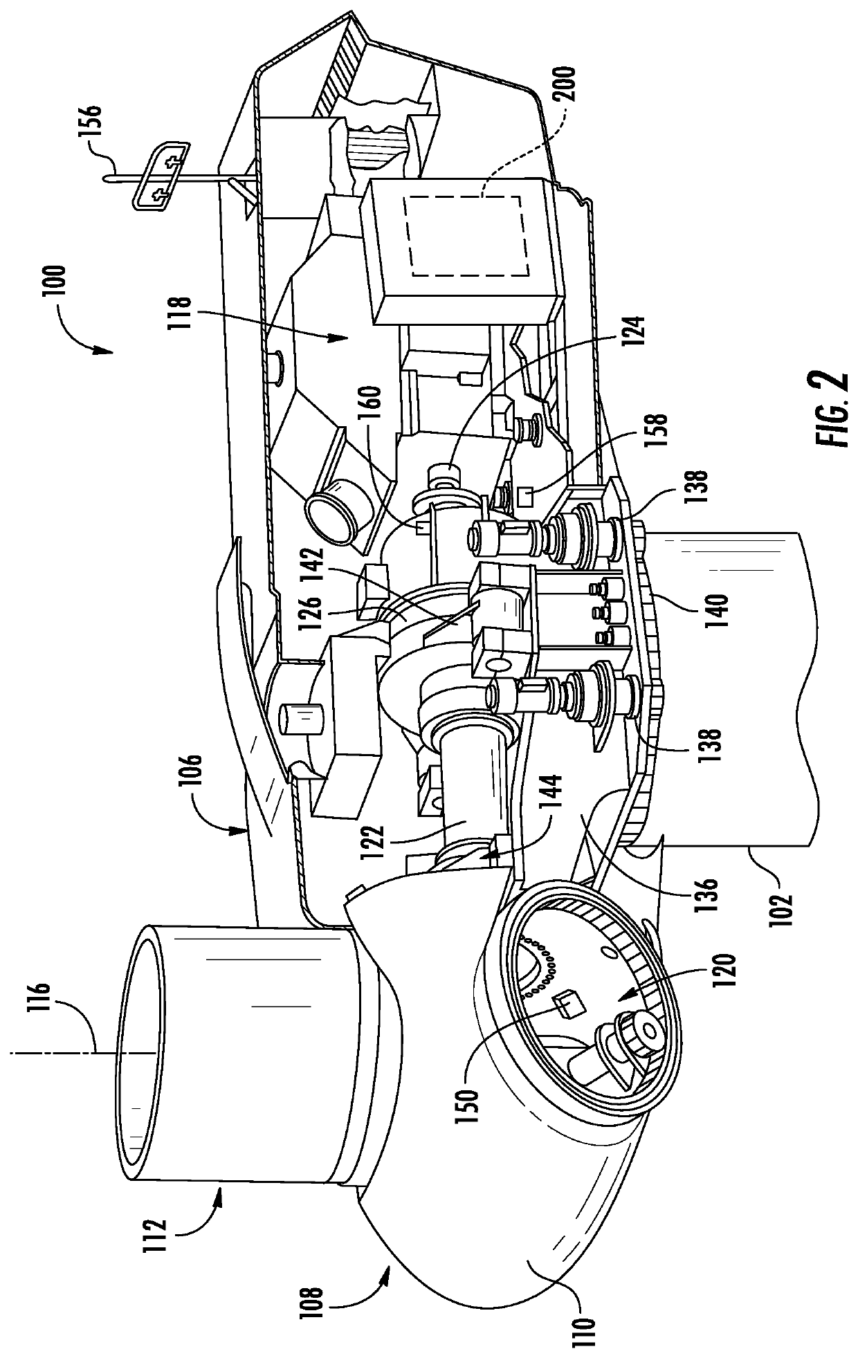
FIELD[0001]The present disclosure relates in general to wind turbines, and more particularly to systems and methods for operating wind turbines based on a forecasted range of potential risk indices.BACKGROUND[0002]Wind power is considered one of the cleanest, most environmentally friendly energy sources presently available, and wind turbines have gained increased attention in this regard. A modern wind turbine typically includes a tower, a generator, a gearbox, a nacelle, and one or more rotor blades. The nacelle includes a rotor assembly coupled to the gearbox and to the generator. The rotor assembly and the gearbox are mounted on a bedplate support frame located within the nacelle. The one or more rotor blades capture kinetic energy of wind using known airfoil principles. The rotor blades transmit the kinetic energy in the form of rotational energy so as to turn a shaft coupling the rotor blades to a gearbox, or if a gearbox is not used, directly to the generator. The generator th...

Claims


Application Information

Patent Timeline
Patent Type & Authority Patents(United States)
IPC IPC(8): G05B19/042
CPCG05B19/042G05B2219/2619F03D7/045F03D7/0264F03D7/043F03D80/50F03D17/00F05B2240/96Y02E10/72
Inventor CHAKRABARTI, SURYARGHYASHIN, YOUNGWONMIHOK, JOHN JOSEPHSUBBER, WAAD HUSSAIN
Owner GENERAL ELECTRIC CO
Learn More