
Gear configuration operable in various angles

Inactive Publication Date: 2014-01-09
URGENC HASAN GOZDER
View PDF0 Cites 8 Cited by
  • Summary
  • Abstract
  • Description
  • Claims
  • Application Information

AI Technical Summary

Benefits of technology

The present invention includes a gear configuration that allows for adjustable shaft angles and synchronization between two hemispherical gears. The gear configuration includes a bracket with pivot holes and a cylindrical member attached to the bracket, as well as a synchronization means to provide contact between the gears at an equal angular distance from the poles. Additionally, a ring bracket with bars attached to a ring member can also be used to adjust the angle between the shafts connected to the gears. The technical effects of this invention allow for more flexible and synchronized rotation between the gears.

Problems solved by technology

However the gearing intersection angle of the two shafts cannot be changed or varied.
Furthermore, over the angular limit, the desired speed of rotation of the gears cannot be attained.

Method used


Image

  • Gear configuration operable in various angles
  • Gear configuration operable in various angles
  • Gear configuration operable in various angles

Examples


Embodiment Construction

[0030]The following detailed description is of the best currently contemplated modes of carrying out exemplary embodiments of the invention. The description is not to be taken in a limiting sense, but is made merely for the purpose of illustrating the general principles of the invention, since the scope of the invention is best defined by the appended claims.

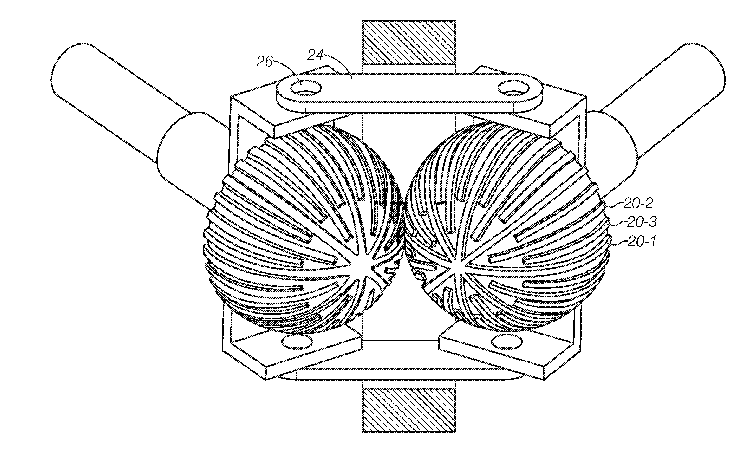
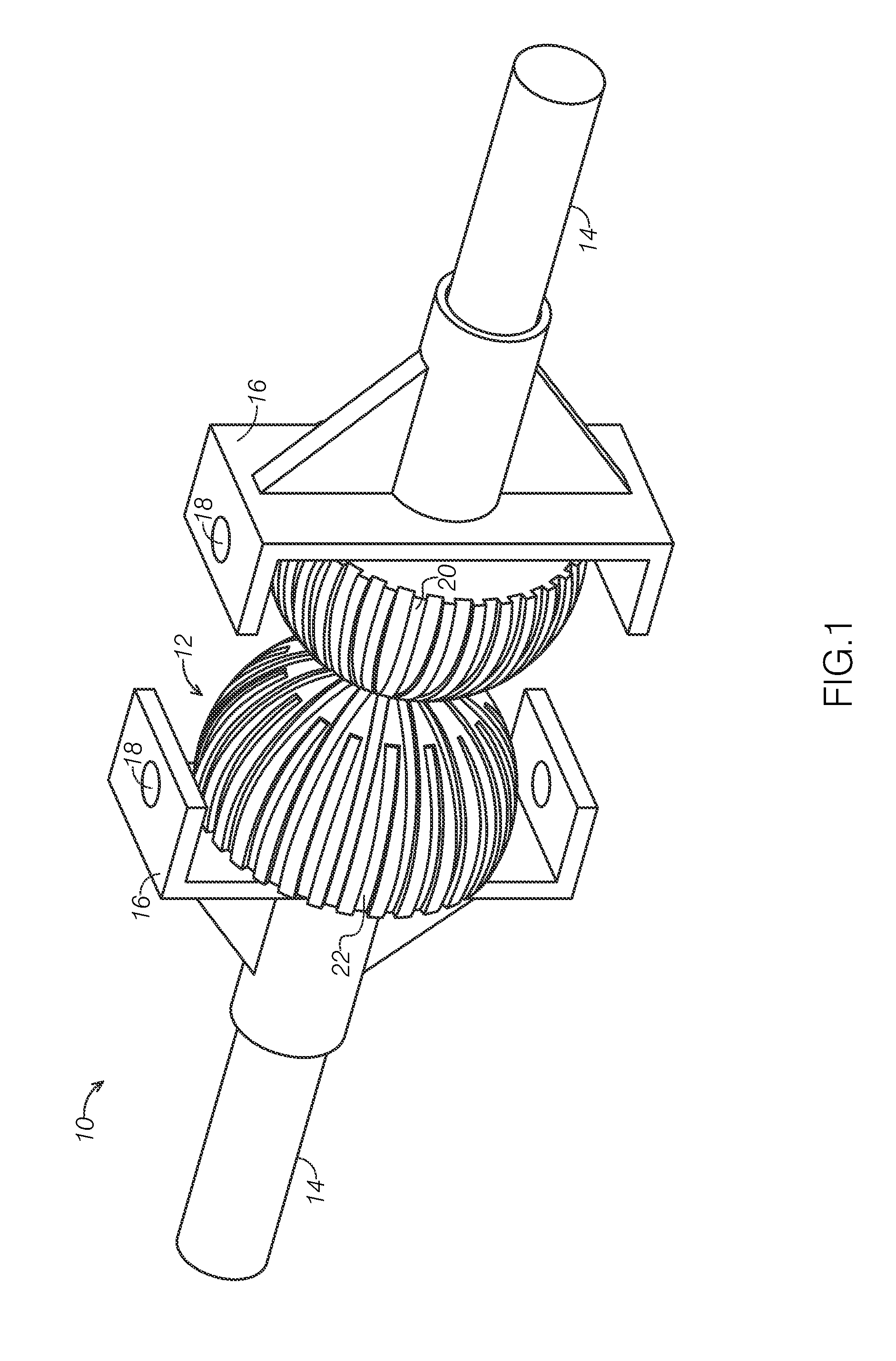
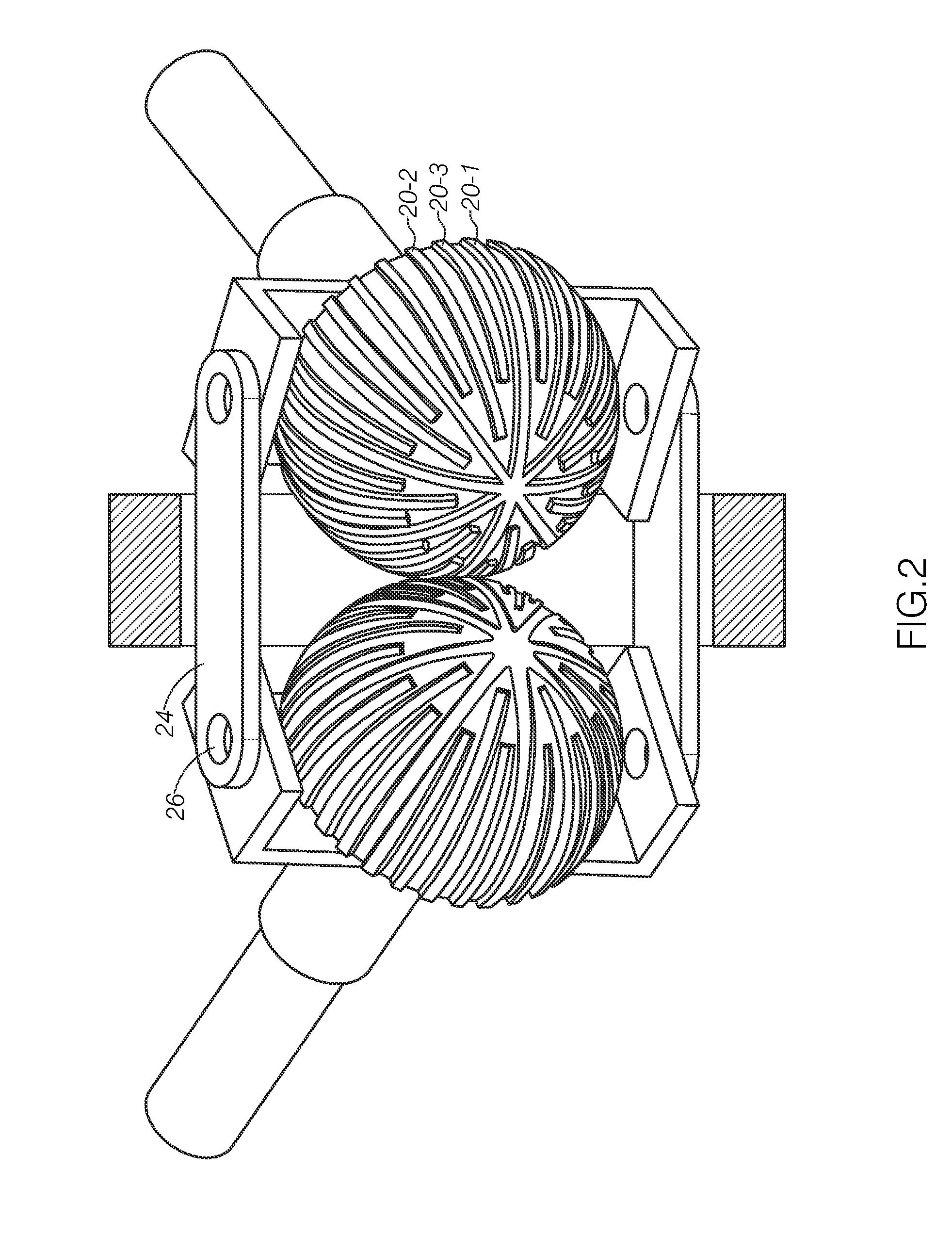
[0031]Broadly, an embodiment of the present invention provides a gear configuration where force (torque) coming from a drive shaft is transmitted to a driven shaft through two hemispherical gears that are placed at the end of the shafts and touch each other in variable, but constantly equal angular distance from the poles. This constant equal angular distance from the poles can be maintained through synchronization gears that are positioned against each other on both sides of U-shaped elements. These U-shaped elements also keep the shafts in position, where each U-shaped element on each of the shafts are connected by a ring form...


PUM


Abstract

A gear configuration allows force (torque) coming from a drive shaft to be transmitted to a driven shaft through two hemispherical gears that are placed at the end of the shafts and touch each other in variable, but constantly equal distance from the poles. This constant equal distance from the poles can be maintained through synchronization gears that are positioned against each other on both sides of U-shaped elements. These U-shaped elements also keep the shafts in position, where each U-shaped element on each of the shafts are connected by a ring formed hinge element, consequently keeping the hemispheres in connection

Description

CROSS-REFERENCE TO RELATED APPLICATION[0001]This application claims the benefit of priority of U.S. provisional application No. 61 / 668,131, filed Jul. 5, 2012, the contents of which are herein incorporated by reference.BACKGROUND OF THE INVENTION[0002]The present invention relates to gear configurations and, more particularly, to a hemispherical gear configuration that can operate at various angles.[0003]Generally, a pair of conventional spur gears have a driving shaft and a driven shaft with a plurality of teeth on each gear for gearing with each other in parallel so that only the ratio of rotation and the direction of the rotation are changeable. However the gearing intersection angle of the two shafts cannot be changed or varied.[0004]Conventional bevel gears can change in an engagement intersection angle of two shafts of the pair of conventional bevel gears. However, the engagement angle of such pair of bevel gears is determined according to an angle of the pitch circle. For exa...

Claims


Application Information

Patent Timeline
IPC IPC(8): F16H35/06
CPCF16H35/06F16H1/24F16D3/18Y10T74/19502
Inventor URGENC, HASAN GOZDER
Owner URGENC HASAN GOZDER
Learn More