Apparatuses for cutting food products

a technology for food products and cutting tools, applied in the direction of metal working tools, etc., can solve the problems of inability to produce v-slices and crinkle slices having relatively large amplitude cross-sections without incurring unacceptable levels of through-slice cracking, undesirable surface cracking and surface roughness, etc., to achieve minimal through-cracking and abrasion, and large amplitude cross-section

Active Publication Date: 2014-01-09
URSCHEL LAB +1
View PDF16 Cites 39 Cited by
  • Summary
  • Abstract
  • Description
  • Claims
  • Application Information

AI Technical Summary

Benefits of technology

[0013]A technical effect of the invention is the ability to produce a food product slice having a large amplitude cross-section with minimal through-cracking and abrasion on the peaks of the slices.
[0014]Other aspects and advantages of this invention will be better appreciated from the following detailed description.

Problems solved by technology

Equipment currently available for cutting food product, such as those represented in FIGS. 1-4, are well suited for producing slices of a wide variety of food products, but have shown to be incapable of producing V-slices and crinkle slices having relatively large amplitude cross-sections without incurring unacceptable levels of through-slice cracking, or at minimum undesirable surface cracking and surface roughness.

Method used


Image

  • Apparatuses for cutting food products
  • Apparatuses for cutting food products
  • Apparatuses for cutting food products

Examples


first embodiment

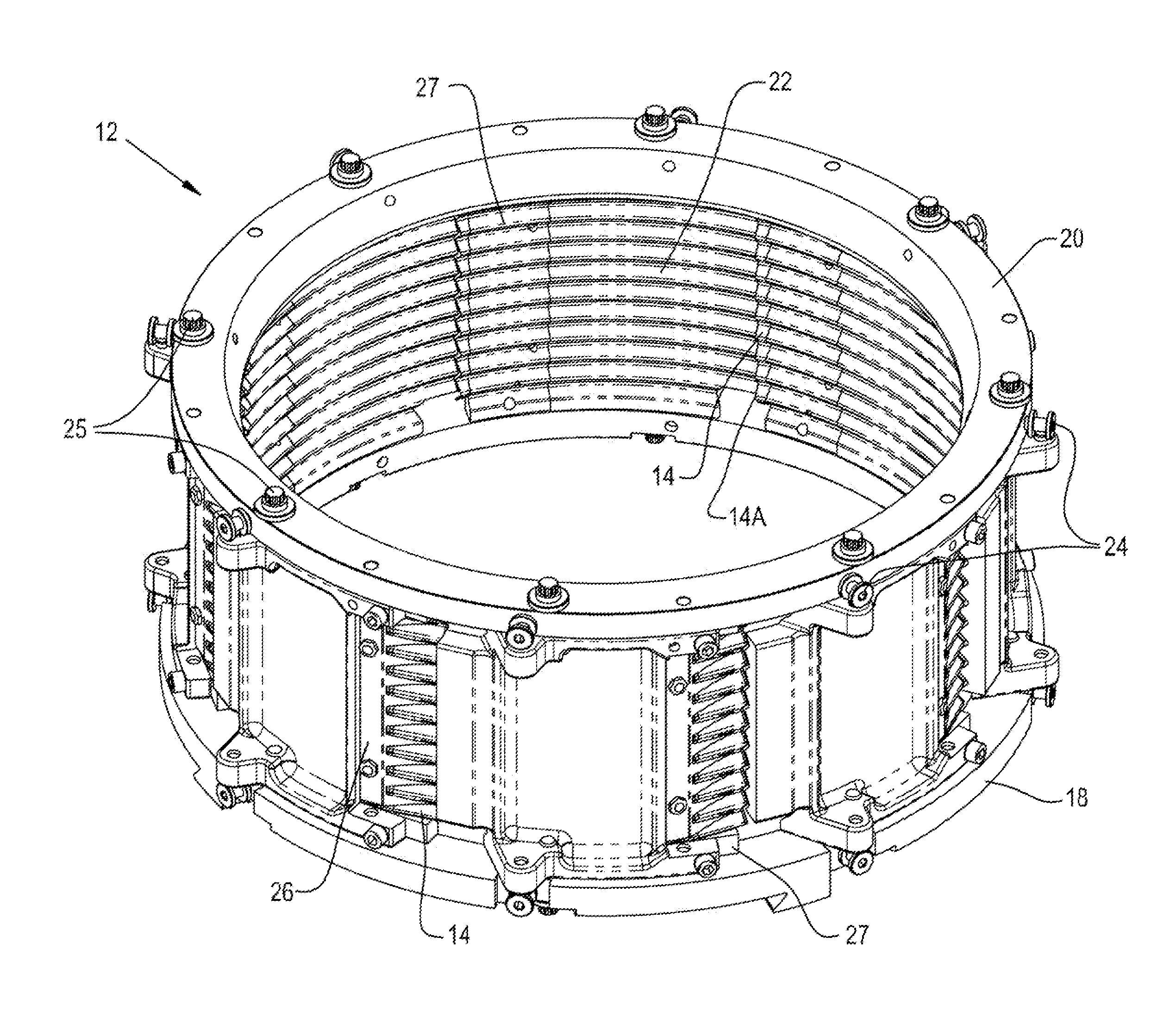
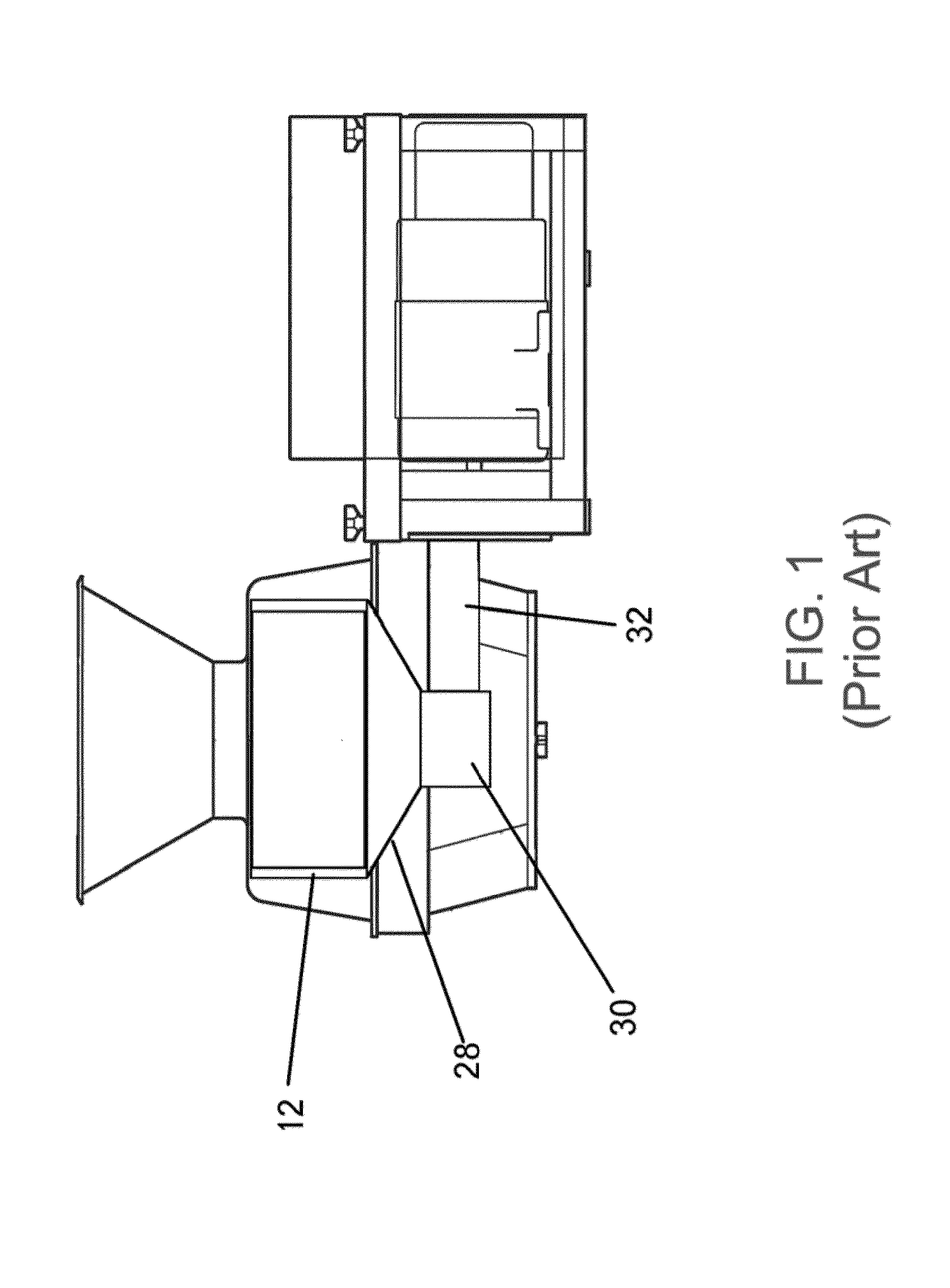
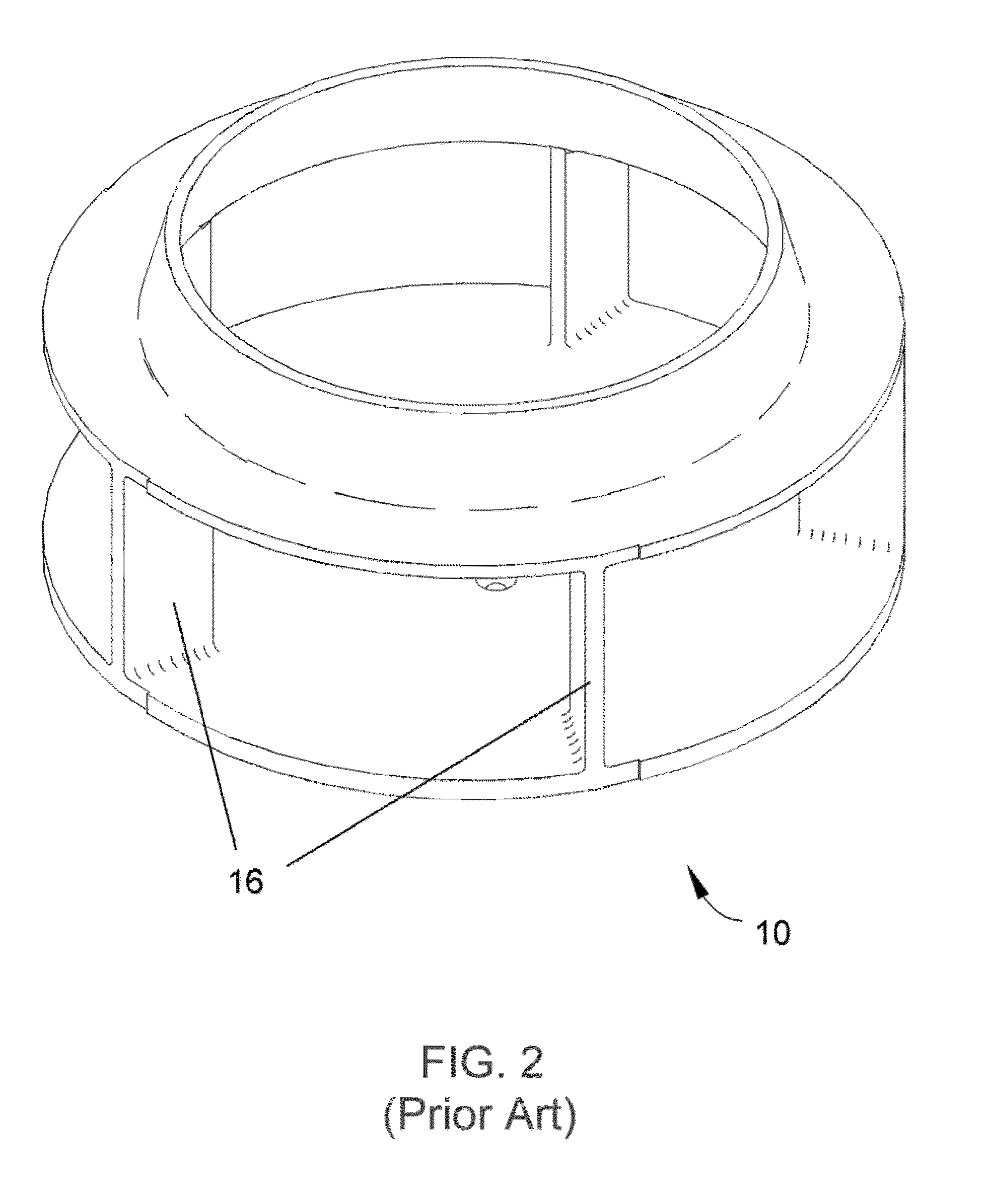
[0037]The cutting apparatus of the first embodiment is represented in FIG. 5 as comprising an annular-shaped cutting head 12. The cutting head 12 is configured for operation with an impeller 10, such as of the types represented in FIGS. 2 and 4, and can be used in various types of machines including that represented in FIG. 1. Regardless of its particular configuration, the impeller 10 is coaxially mounted within the cutting head 12 for rotation about an axis of the cutting head 12 in a rotational direction relative to the cutting head 12. Furthermore, the impeller 10 comprises at least one paddle 16 and preferably multiple paddles 16 circumferentially spaced along a perimeter thereof for delivering food product radially outward toward the cutting head 12. The cutting head 12 comprises at least one and preferably multiple knife assemblies arranged in sets spaced around the circumference of the cutting head 12. Each knife assembly includes a knife 14 and means for securing the knife ...

second embodiment

[0054] the invention is also applicable to a cutting apparatus configured as shown in FIG. 17 as having a cutting head 112 mounted upright and rotated about a horizontally disposed central axis, wherein food product is feed through an opening on a side of the cutting head 112. For example, in FIG. 17 the cutting apparatus is represented as comprising a housing 132, a stationary hollow elongate feed chute 140, and a cylindrical-shaped rotary cutting head 112. The feed chute 140 extends along a longitudinal axis through the housing 132 and a circular-shaped front opening of the cutter head 112. A plurality of food products stacked within the feed chute 140 in a linear array are caused to consecutively be fed through an outlet opening 138 of the feed chute 140 and engage a circumferential wall defined in part by at least one knife assembly of the cutting head 112 approximately midway between the opposite ends of the wall and spaced rearwardly of the axis of rotation with respect to the...

third embodiment

[0056] the invention is further applicable to a cutting apparatus configured as shown in FIGS. 19 through 23. FIG. 19 represents the cutting apparatus as comprising a housing 232, a feed tube 240, and a horizontally disposed rotatable cutting wheel 212. Food product is delivered through the feed tubes 240 mounted to the top of the housing 232. The feed tubes 240 advance the food product in a feed direction towards the cutting wheel 212 within the housing 232.

[0057]The cutting wheel 212 is represented in FIGS. 20 and 21 as comprising at least one knife assembly and preferably a plurality of knife assemblies oriented about the central axis of the cutting wheel 30. As represented in FIGS. 22 and 23, each knife assembly comprises a knife holder 227, a clamping assembly 226, and a knife 214. The knife assemblies are secured to a hub 242 and a rim 244 of the cutting wheel 212 by bolts 225. The knives 214 have leading edges facing a direction of rotation of the cutting wheel 212 and extend...


PUM

PropertyMeasurementUnit
distanceaaaaaaaaaa
rake-off angleaaaaaaaaaa

Abstract

Apparatuses for cutting food product are provided having a cutting head. The cutting head includes one or more knife assemblies. Each knife assembly includes a knife extending toward the food product and is adapter to secure the knife to the cutting head. The knife has a corrugated shape to produce a food product slice with generally parallel cuts wherein the food product slice has a periodic shape and a large-amplitude cross-section.

Description

CROSS REFERENCE TO RELATED APPLICATIONS [0001]This application claims the benefit of U.S. Provisional Application No. 61 / 580,367, filed Dec. 27, 2011, the contents of which are incorporated herein by reference.BACKGROUND OF THE INVENTION [0002]The present invention generally relates to methods and equipment for cutting food products. More particularly, this invention relates to apparatuses suitable for cutting food product slices having relatively large amplitude cross-sections.[0003]Various types of equipment are known for slicing, shredding and granulating food products, such as vegetable, fruit, dairy, and meat products. A widely used line of machines for this purpose is commercially available from Urschel Laboratories, Inc., under the name Urschel Model CC®, an embodiment of which is represented in FIG. 1. The Model CC® machine line provides versions of centrifugal-type slicers capable of producing uniform slices, strip cuts, shreds and granulations of a wide variety of food pro...

Claims


Application Information

Patent Timeline
Patent Type & Authority Applications(United States)
IPC IPC(8): B26D1/36
CPCB26D1/36B26D1/0006B26D1/147B26D1/29B26D1/62B26D3/26B26D3/28B26D7/0641B26D7/0691B26D7/2614B26D7/2628B26D7/32B26D2001/006B26D2210/02Y10T83/6473
Inventor MICHEL, ENRIQUEHILDEBRAND, JOHN POOLEBARBER, KEITH ALANJACKO, MICHAEL SCOTKING, DANIEL WADE
Owner URSCHEL LAB
Why Eureka
Try Eureka