Multicore fiber

a multi-core fiber and core technology, applied in the field of multi-core fibers, can solve the problems of inability to perform single-mode communication in the specific core, and the cutoff wavelength of the specific core is increasing, so as to reduce inter-core crosstalk and suppress the effect of increasing the cutoff wavelength of the specific cor

Active Publication Date: 2014-01-09
THE FUJIKURA CABLE WORKS LTD
View PDF4 Cites 17 Cited by
  • Summary
  • Abstract
  • Description
  • Claims
  • Application Information

AI Technical Summary

Benefits of technology

[0051]As described above, according to the present invention, a multicore fiber capable of suppressing the cutoff wavelength of a specific core from increasing while reducing inter-core crosstalk is provided.

Problems solved by technology

However, as a result of studies, the present inventors have found that, in the multicore fiber disclosed in Patent Document 1, the cutoff wavelength of a specific core may increase due to the arrangement of cores, and it is not possible to perform single-mode communication in the specific core under the same conditions as the other cores.

Method used


Image

  • Multicore fiber
  • Multicore fiber
  • Multicore fiber

Examples


first embodiment

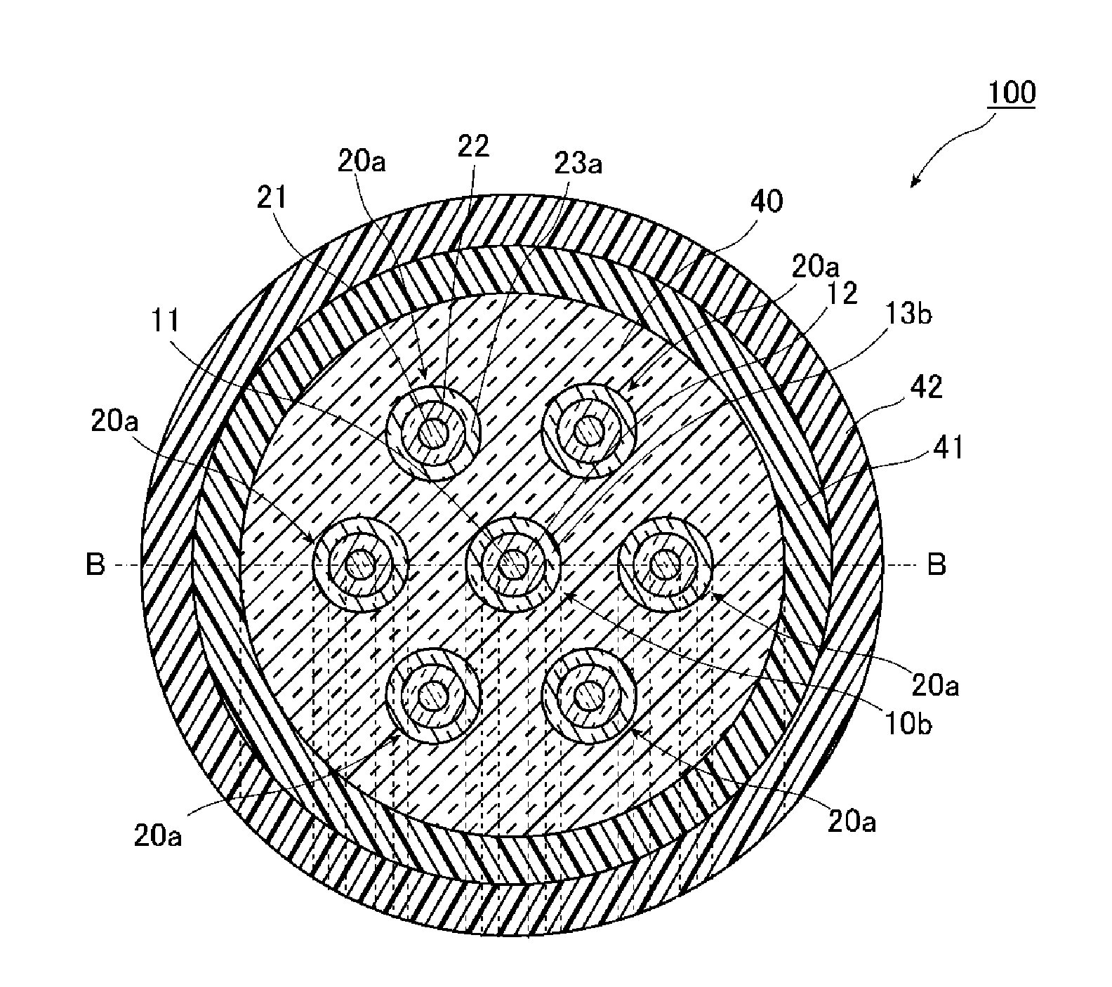
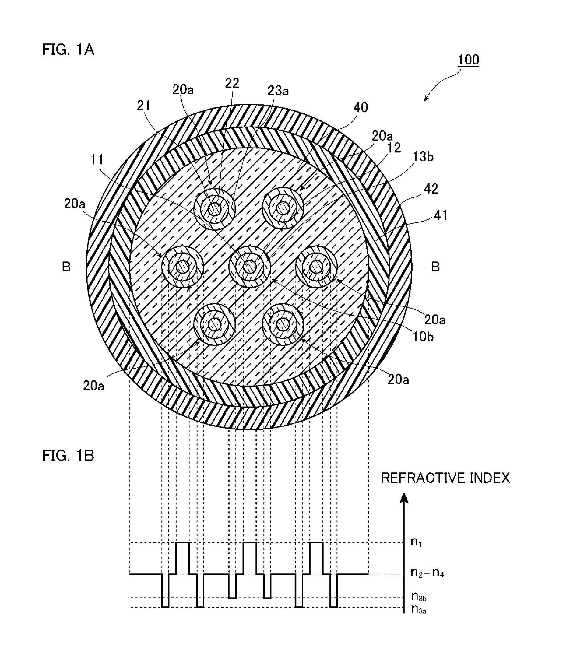
[0076]FIGS. 1A and 1B are a diagram illustrating a configuration of a multicore fiber 100 according to a first embodiment of the present invention. Specifically, FIG. 1A is a diagram illustrating a cross-sectional structure vertical to a longitudinal direction of the multicore fiber 100, and FIG. 1B is a diagram illustrating a refractive index distribution along a line B-B of the multicore fiber 100 illustrated in FIG. 1A.

[0077]As illustrated in FIG. 1A, the multicore fiber 100 according to the present embodiment includes a cladding 40, a specific core element 10b disposed at the center in the radial direction of the cladding 40, three or more core elements 20a disposed in the cladding 40 so as to surround the core element 10b, an inner protective layer 41 that covers the circumferential surface of the cladding 40, and an outer protective layer 42 that covers the circumferential surface of the inner protective layer 41. FIG. 1A illustrates a case where one core element 10b is surrou...

second embodiment

[0098]Next, a second embodiment of the present invention will be described with reference to FIGS. 2A and 2B. The same or equivalent constituent elements as those of the first embodiment will be denoted by the same reference numerals unless otherwise particularly stated, and redundant description thereof will not be provided.

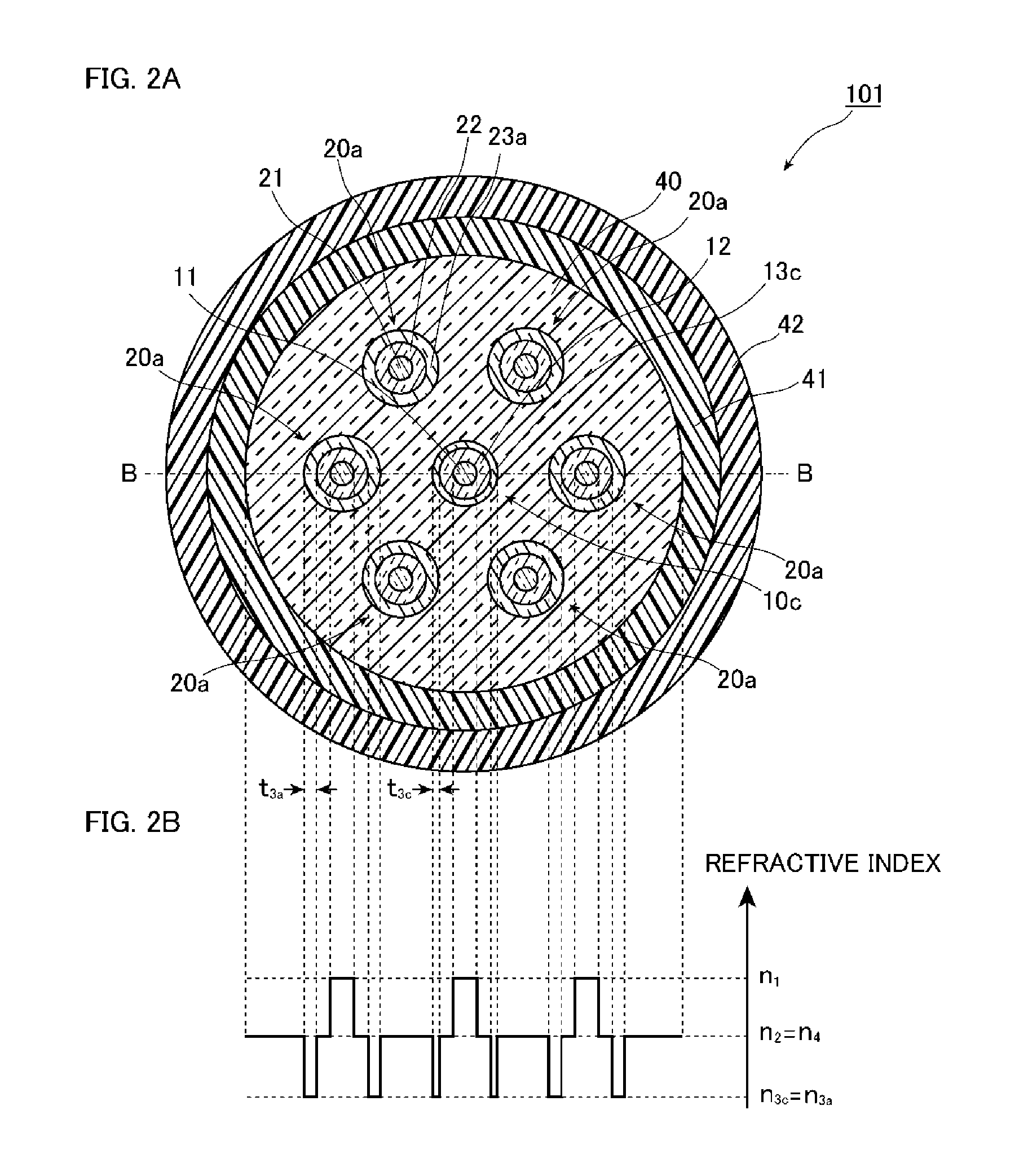
[0099]FIGS. 2A and 2B are a diagram illustrating a configuration of a multicore fiber 101 according to the second embodiment of the present invention. Specifically, FIG. 2A is a diagram illustrating a cross-sectional structure vertical to a longitudinal direction of the multicore fiber 101, and FIG. 2B is a diagram illustrating a refractive index distribution along a line B-B of the multicore fiber 101 illustrated in FIG. 2A.

[0100]As illustrated in FIG. 2A, the multicore fiber 101 according to the present embodiment is different from the multicore fiber 100 according to the first embodiment, in that the multicore fiber 101 includes a specific core element 10c th...

third embodiment

[0105]Next, a third embodiment of the present invention will be described with reference to FIGS. 3A and 3B. The same or equivalent constituent elements as those of the first embodiment will be denoted by the same reference numerals unless otherwise particularly stated, and redundant description thereof will not be provided.

[0106]FIGS. 3A and 3B are a diagram illustrating a configuration of a multicore fiber 102 according to the third embodiment of the present invention. Specifically, FIG. 3A is a diagram illustrating a cross-sectional structure vertical to a longitudinal direction of the multicore fiber 102, and FIG. 3B is a diagram illustrating a refractive index distribution along a line B-B of the multicore fiber 102 illustrated in FIG. 3A.

[0107]As illustrated in FIGS. 3A and 3B, the multicore fiber 102 according to the present embodiment is different from the multicore fiber 100 according to the first embodiment, in that the multicore fiber 102 includes a specific core element ...


PUM


Abstract

A multicore fiber includes a cladding and a plurality of core elements which is provided in the cladding and includes a core, an inner cladding layer that surrounds the core, and a low-refractive index layer that surrounds the inner cladding layer and has a lower average refractive index than the cladding and the inner cladding layer. The plurality of core elements is arranged such that a specific core element is surrounded by three or more core elements, and a low-refractive index layer of a partial core element of the plurality of core elements is configured to have larger light confinement loss in the core than low-refractive index layers of the other partial core elements.

Description

TECHNICAL FIELD[0001]The present invention relates to a multicore fiber capable of suppressing the cutoff wavelength of a specific core from increasing while reducing crosstalk.BACKGROUND ART[0002]Currently, an optical fiber used in an optical fiber communication system that is widely used has such a structure that the circumference of one core is surrounded by a cladding, and an optical signal propagates through the core, whereby information is transmitted. With the spread of the optical fiber communication system in recent years, the amount of transmitted information is increasing dramatically. With an increase in the amount of transmitted information, a large number of optical fibers ranging from several tens to several hundreds are used in the optical fiber communication system, to thereby enable large-volume and long-distance optical communication.[0003]In order to decrease the number of optical fibers used in such an optical fiber communication system, a technique of transmitt...

Claims


Application Information

Patent Timeline
Patent Type & Authority Applications(United States)
IPC IPC(8): G02B6/02
CPCG02B6/02042G02B6/02366G02B6/0365
Inventor SASAKI, YUSUKEMATSUO, SHOICHIROTAKENAGA, KATSUHIRO
Owner THE FUJIKURA CABLE WORKS LTD
Why Eureka
Try Eureka