Rotatable connector device

a technology of rotating connectors and connectors, which is applied in the direction of current collectors, electric/fluid circuits, vehicle components, etc., to achieve the effect of maintaining electrical connections

Active Publication Date: 2014-01-09
FURUKAWA ELECTRIC CO LTD +1
View PDF7 Cites 9 Cited by
  • Summary
  • Abstract
  • Description
  • Claims
  • Application Information

AI Technical Summary

Benefits of technology

[0015]According to the present invention, a rotatable connector device which can maintain electrical connection between the rotator and the stator with certainty even when being contaminated with a foreign object such as sand or the like can be provided.

Problems solved by technology

When the accommodation space S is contaminated with a foreign object such as sand or the like, there is an undesirable possibility that when the rotator 20 rotates, the reversed part Cr of the flat cable C is abraded to cause malfunctioning.
For example, in the case where a contact part of the reversed part Cr of the flat cable C and the press guide 46 is contaminated with a foreign object such as sand or the like when the rotator 20 rotates clockwise, there is an undesirable possibility that the reversed part Cr is rubbed with the foreign object and thus the flat cable C is abraded to cause malfunctioning.

Method used


Image

  • Rotatable connector device
  • Rotatable connector device
  • Rotatable connector device

Examples


example 1

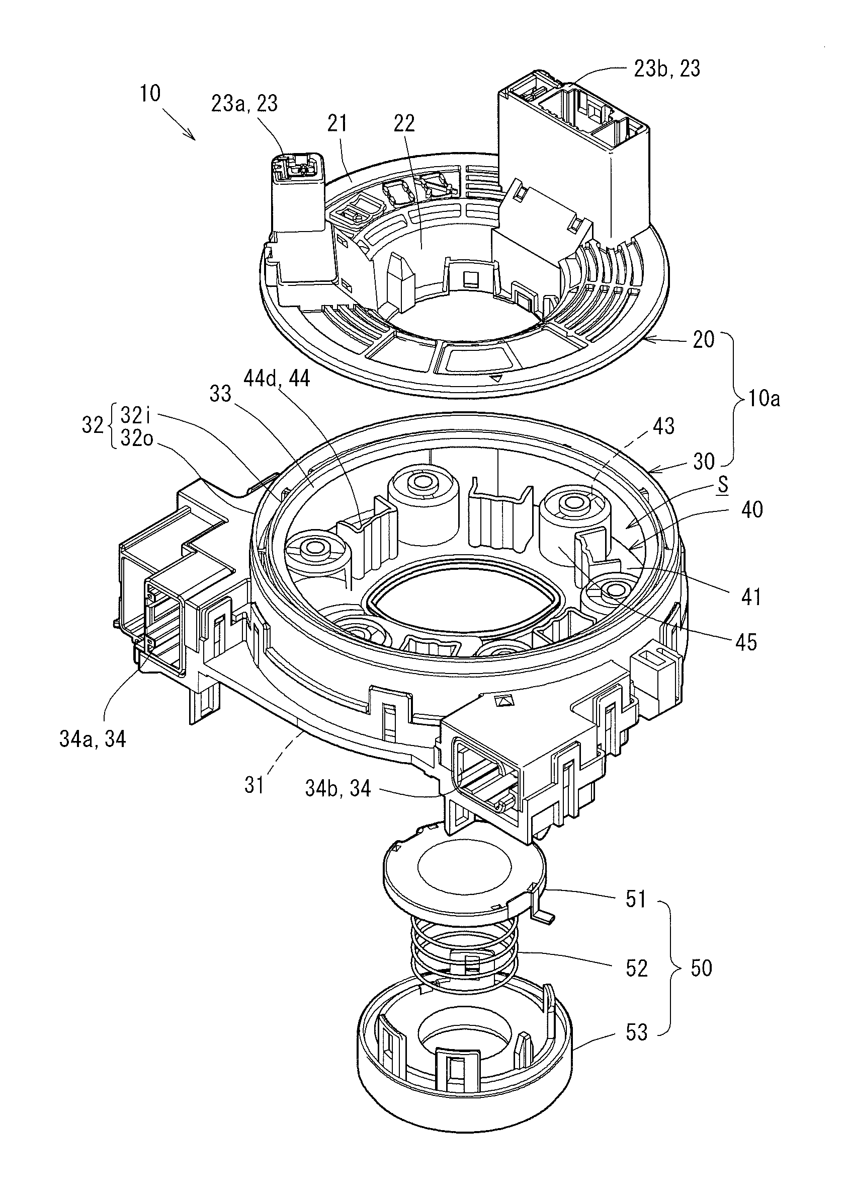
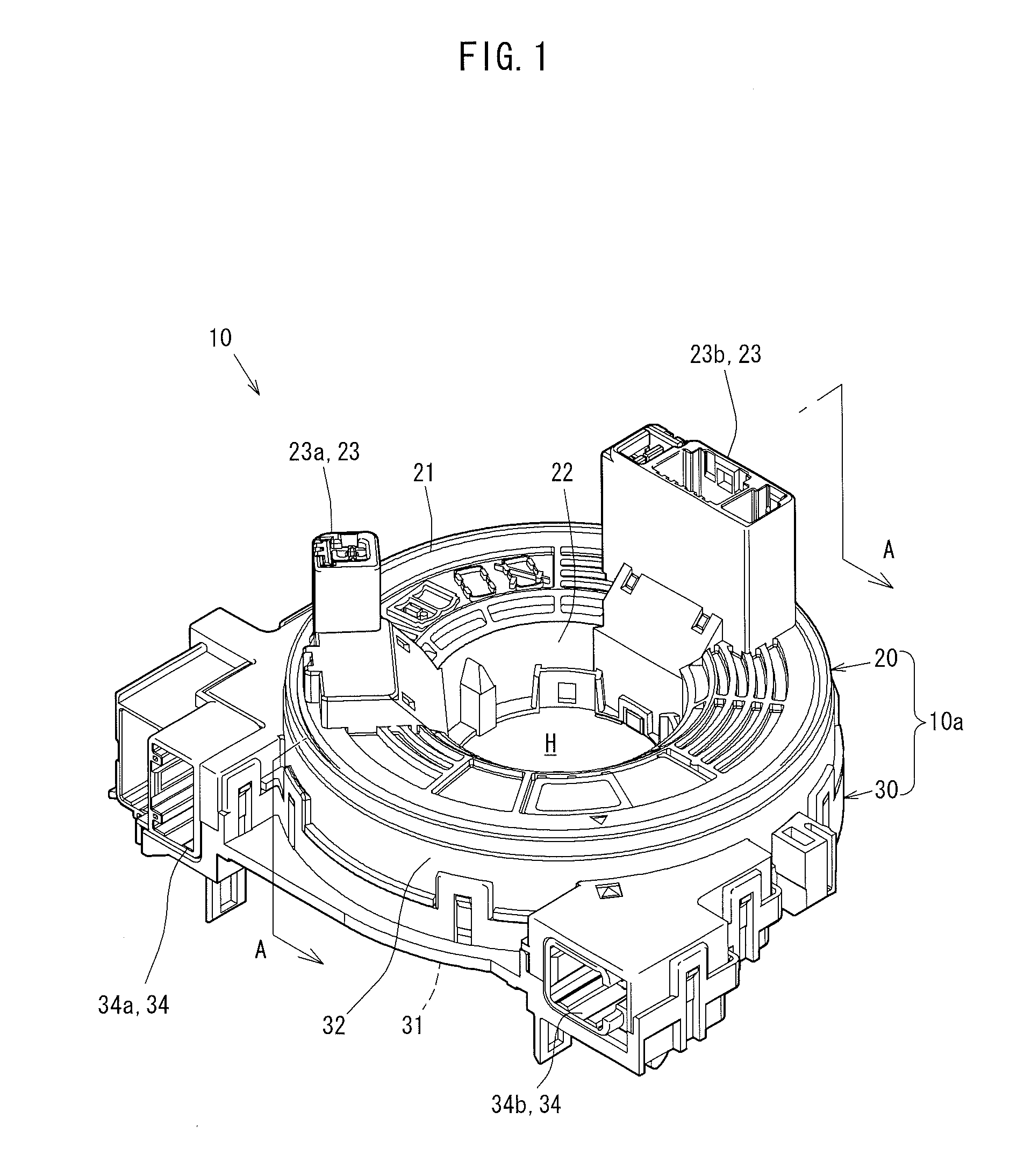
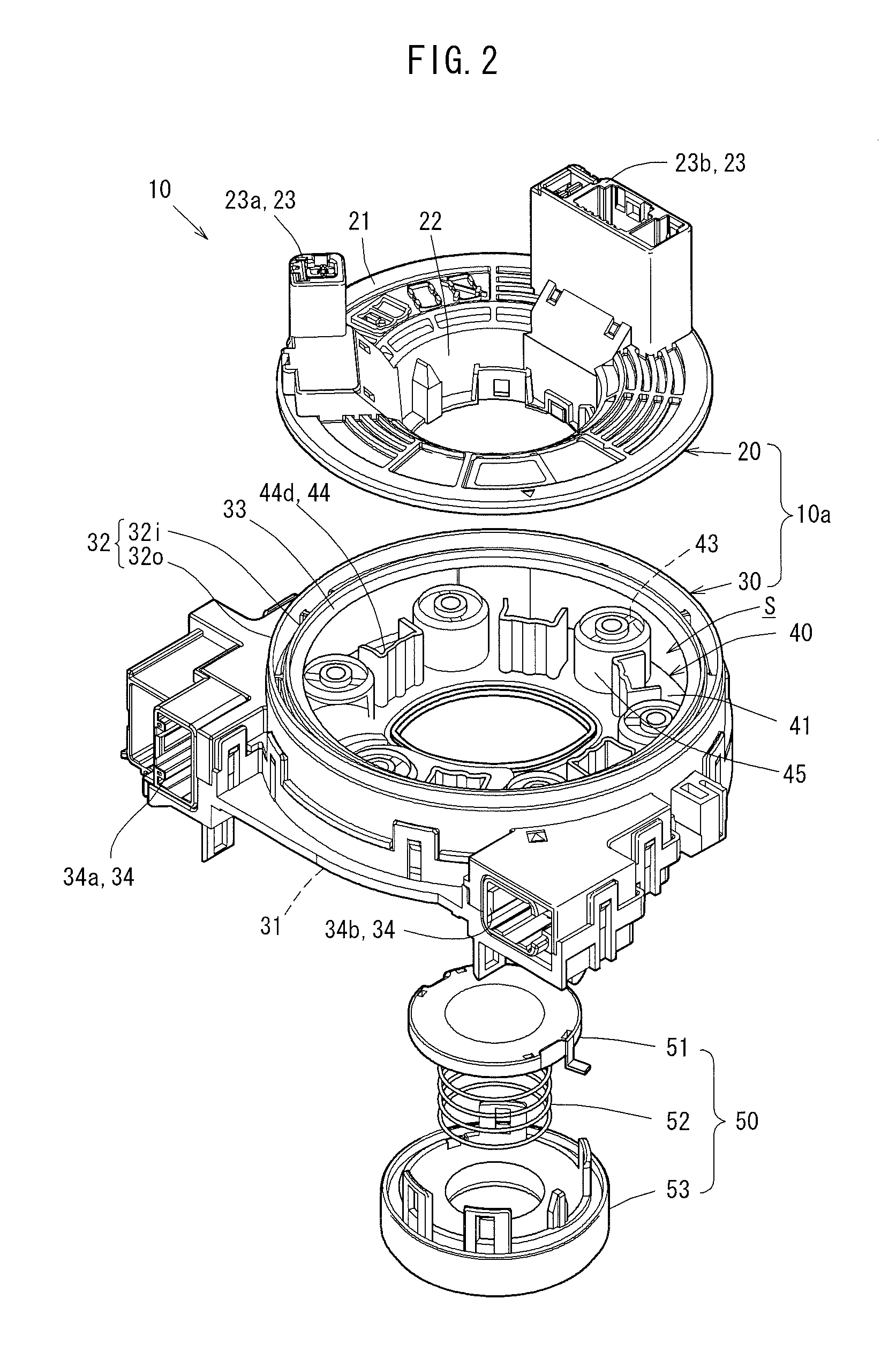
[0040]FIG. 1 is an external isometric view of a steering roll connector 10. FIG. 2 is an exploded isometric view of the steering roll connector 10. FIG. 3 is a plan view showing the steering roll connector 10 in this embodiment in the state where a rotator 20 is detached. FIG. 4 is a cross-sectional view taken along line A-A in FIG. 1.

[0041]As shown in FIG. 1 through FIG. 4, the steering roll connector 10 in this embodiment includes a cable housing 10a, a retainer 40, and a rotation lock body 50.

[0042]As shown in FIG. 3 and FIG. 4, the cable housing 10a has a generally cylindrical shape having an insertion hole H at a central portion thereof as seen in a plan view. The insertion hole H runs through the cable housing 10a in a steering rotation axial direction (up-down direction in FIG. 4). The insertion hole H has a diameter which allows a steering shaft (not shown) protruding from a steering column (not shown) to be inserted into the insertion hole H. The cable housing 10a includes ...

example 2

[0121]Now, in another embodiment, a case where there are two flat cables will be described with reference to FIG. 6.

[0122]FIG. 6 is a plan view of the steering roll connector 10 in Example 2 in the state where the rotator 20 is detached.

[0123]Elements identical to those of Example 1 described above will bear identical reference signs thereto, and detailed descriptions thereof will be omitted.

[0124]As shown in FIG. 6, the steering roll connector 10 in Example 2 includes a flat cable F accommodated in the accommodation space S in addition to the elements in Example 1. Because the flat cable F is added, the structure of the diametrical direction restriction sections 44 on the retainer 40 is different from that in Example 1.

[0125]This will be described in detail. The third diametrical direction restriction section 44c is provided to stand on the retainer 40 close to the rotatable roller 45 along which the reversed part Dr of the dummy cable D is wound, and faces the first diametrical di...


PUM


Abstract

In an accommodation space formed by a rotator and a stator, a flat cable and a dummy cable are accommodated. A retainer placed in a bottom part of the accommodation space is provided with a press guide for allowing a reversed part of the dummy cable, at which a winding direction thereof is reversed, to be pressed thereon.

Description

TECHNICAL FIELD[0001]The present invention relates to a rotatable connector device for, for example, electrically connecting elements on the side of a steering wheel of an automobile and the side of a vehicle body to each other.BACKGROUND ART[0002]A rotatable connector device which is mountable on a vehicle such as an automobile or the like includes a stator which is to be fixed mainly on the side of a vehicle body and a rotator which is to be assembled to the side of a steering wheel. The stator and the rotator are assembled together coaxially so as to be rotatable with respect to each other. In addition, a flat cable is accommodated in an accommodation space formed by the stator and the rotator.[0003]The flat cable electrically connects an electric device such as a horn module, an airbag module, an audio control module or the like equipped on the side of the steering wheel and a power supply on the side of the vehicle body to each other.[0004]Such a rotatable connector device whic...

Claims


Application Information

Patent Timeline
Patent Type & Authority Applications(United States)
IPC IPC(8): H01R13/52
CPCH01R13/52H01R35/025B60R16/027
Inventor ADACHI, RYOICHI
Owner FURUKAWA ELECTRIC CO LTD
Why Eureka
Try Eureka