Coaxial Cable Connector and Coaxial Cable Connection Unit

a technology of coaxial cable and connector, which is applied in the direction of electrical equipment, connections, and permanent deformation-induced connections, can solve the problems of not maintaining the electrical connection of braided wire, and achieve the effect of reducing the number of braided wire located on the outsides of the pair, enhancing the electrical conductivity of the pair, and reducing the possibility of short circui

Inactive Publication Date: 2009-02-05
YAZAKI CORP
View PDF5 Cites 8 Cited by
  • Summary
  • Abstract
  • Description
  • Claims
  • Application Information

AI Technical Summary

Benefits of technology

[0019]Moreover, in the pair of second crimp pieces, one thereof overlaps the other in the state after the crimping operation is performed therefor. Accordingly, even if the amount of the braided wire is large, since one of the second crimp pieces covers the other like a lid, a possibility that the braided wire may stick out of the pair of second crimp pieces can be reduced.
[0020]Moreover, in the pair of second crimp pieces, since one thereof is formed to be longer than the other is, one thereof becomes likely to overlap the other in the state after the crimping operation, and the possibility that the braided wire may stick out of the pair of second crimp pieces can be reduced.
[0021]In accordance with the coaxial cable connection unit of the present invention, the pair of first crimp pieces is formed into the shape that is along the inner walls of the pair of second crimp pieces. As described above, since the pair of first crimp pieces are not bent inward, in the case where the insulating inner sheath and at least a part of the braided wire are inserted between the pair of first crimp pieces, the amount of the braided wire located in insides of the pair of first crimp pieces is increased. In such a way, in the case where a coaxial cable in which the braided wire has the double-layered structure is crimped, since the amount of the braided wire located in the insides of the pair of first crimp pieces is large, a falling amount by which the pair of first crimp pieces fall inward is decreased. In addition, though the amount of the braided wire located on the outsides of the pair of first crimp pieces is decreased, the braided wire is not entirely located in the insides of the first crimp pieces, whereby the electrical connection thereof is also maintained. Hence, the possibility of the short circuit can be reduced at the time of the crimping operation while maintaining the electrical connection of the braided wire.
[0022]Moreover, since the braided wire is subjected to the tin plating, electrical conductivity thereof is enhanced, thus making it possible to facilitate the maintenance of the electrical connection of the braided wire.

Problems solved by technology

Specifically, in the case where the first crimp pieces are not present, when the insulating inner sheath is shrunk by the heat, the braided wire separates from the second crimp pieces, and the electrical connection of the braided wire comes not to be maintained.

Method used


Image

  • Coaxial Cable Connector and Coaxial Cable Connection Unit
  • Coaxial Cable Connector and Coaxial Cable Connection Unit
  • Coaxial Cable Connector and Coaxial Cable Connection Unit

Examples


first embodiment

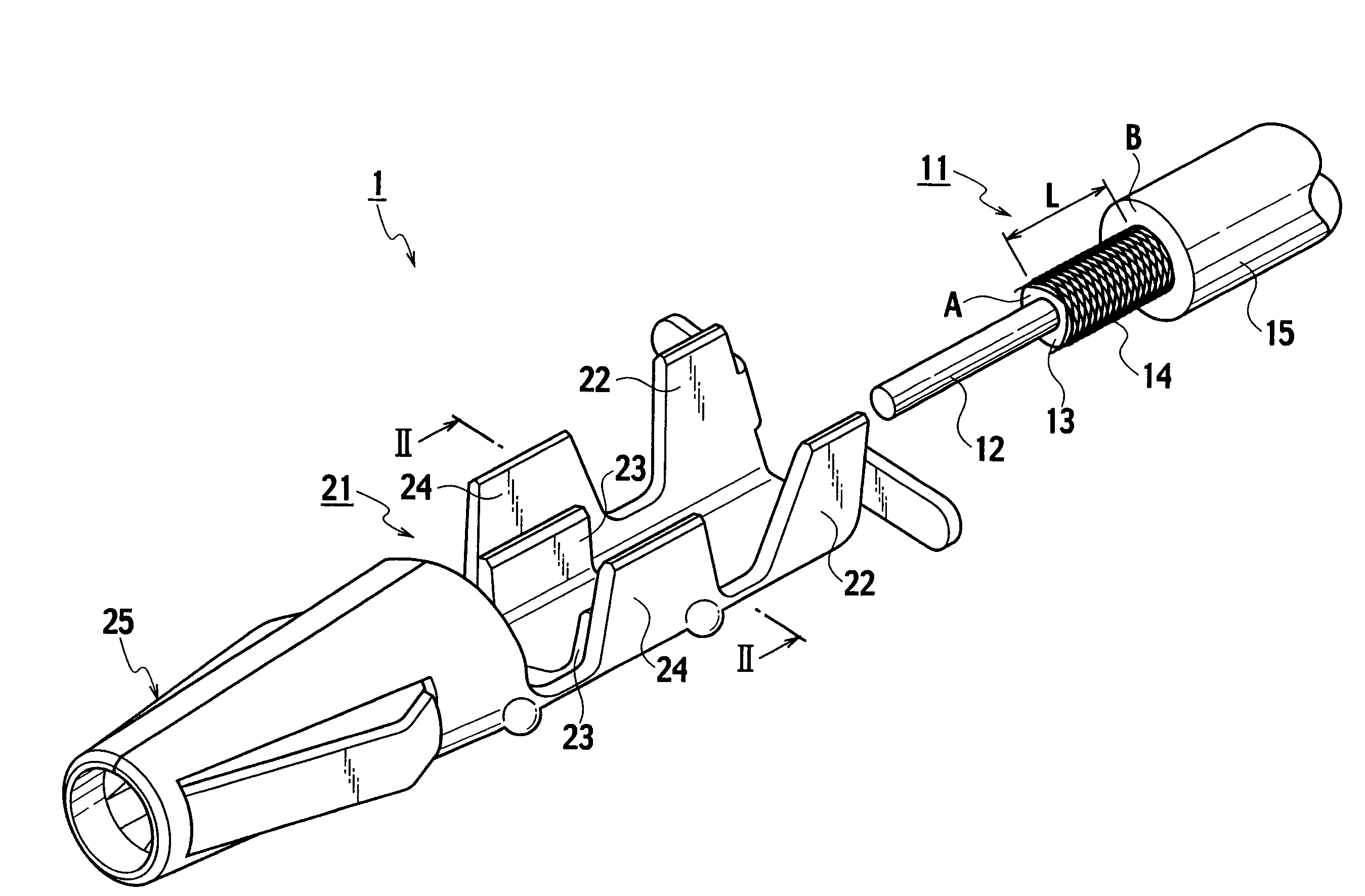
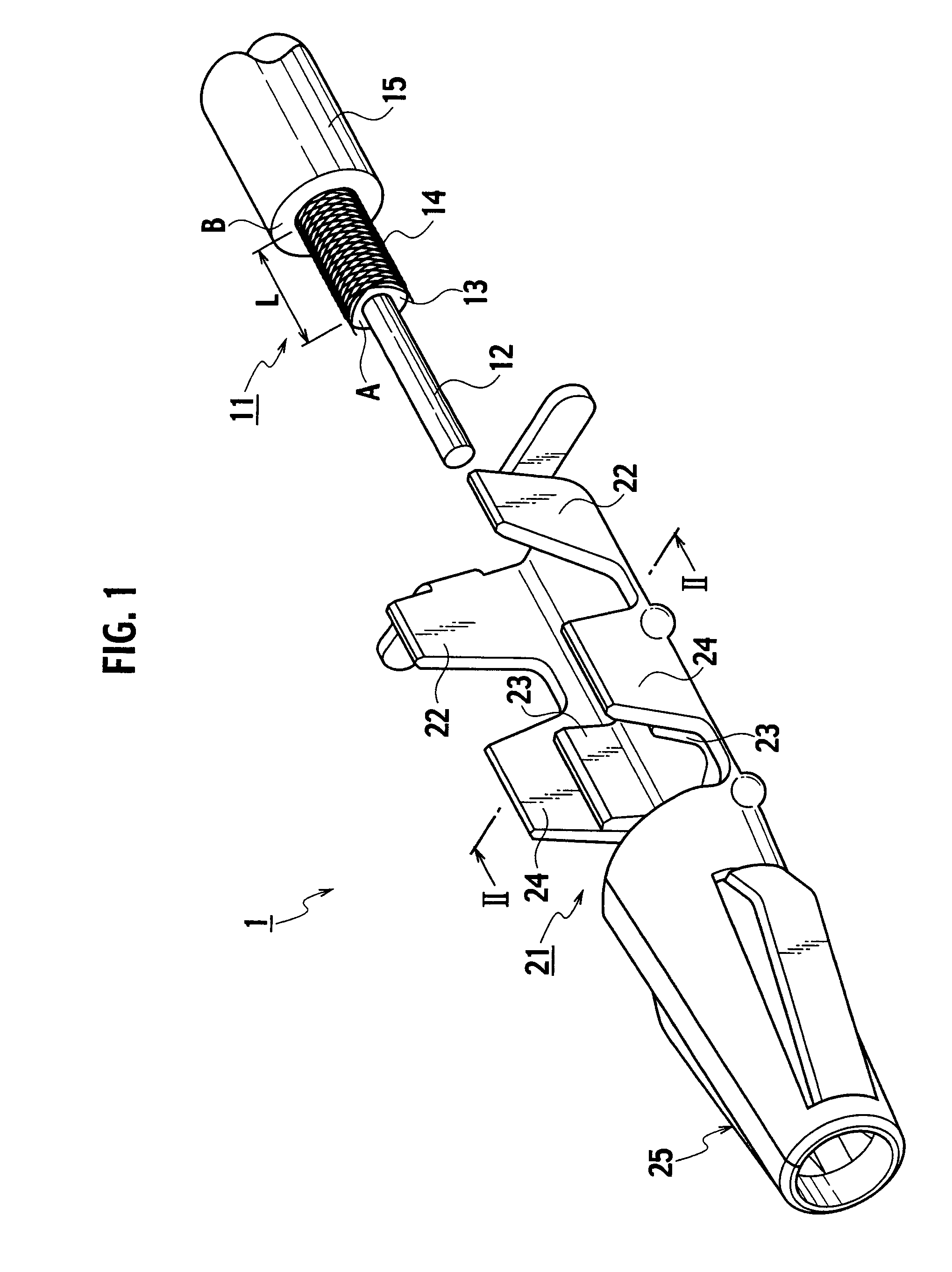
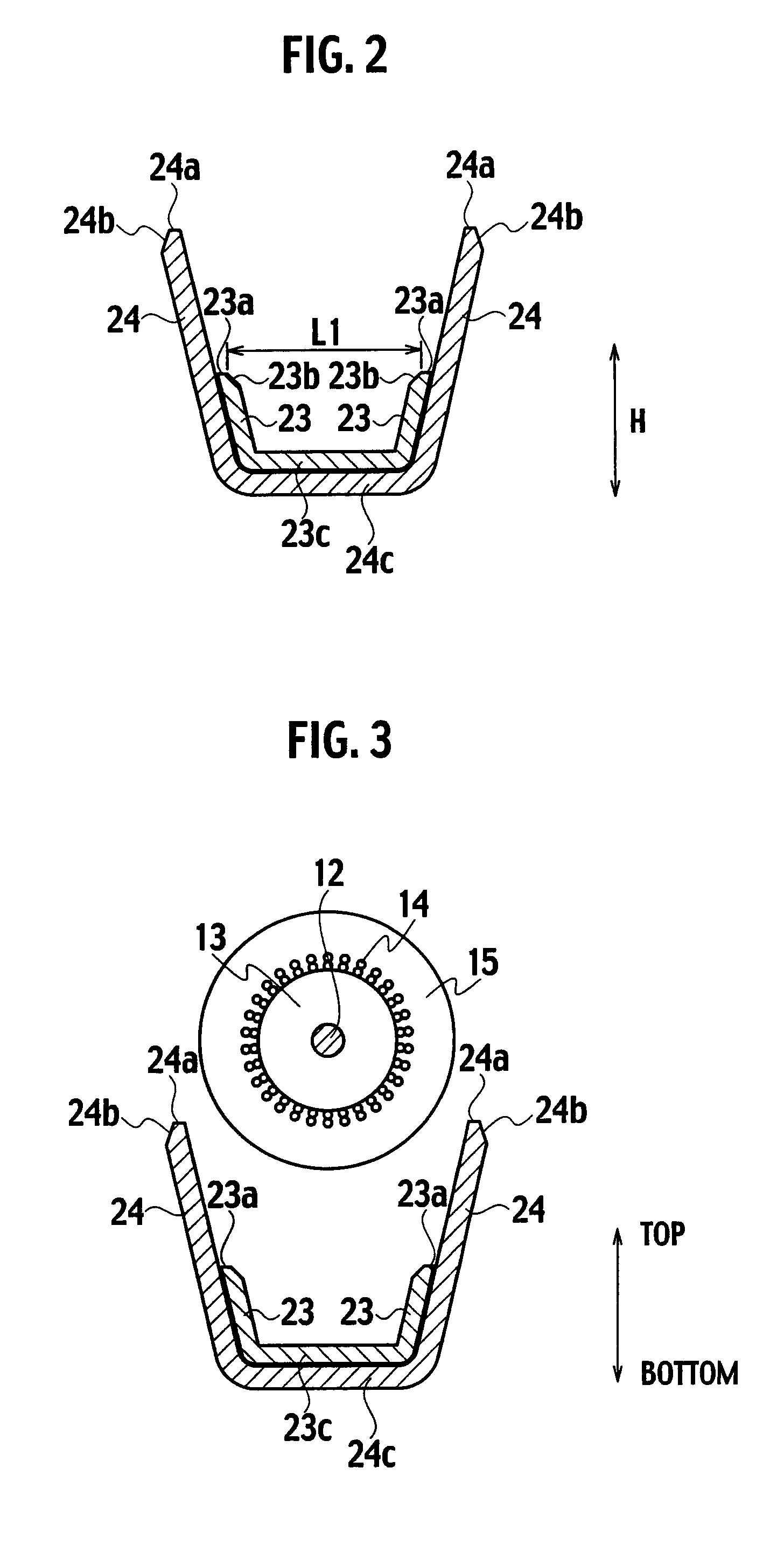
[0046]As described above, in accordance with the coaxial cable connector 21 and the coaxial cable connection unit 1 the pair of first crimp pieces 23 are formed into the shape that is along the inner walls of the pair of second crimp pieces 24. As described above, the pair of first crimp pieces 23 are formed into the shape that is along the inner walls of the pair of second crimp pieces 24 without being bent inward. Accordingly, when the pair of first crimp pieces 23 are inserted between the insulating inner sheath 13 and the braided wire 14, the amount of the braided wire 14 located on the outsides of the pair of first crimp pieces 23 is decreased. In such a way, even if the braided wire 14 is one with a large amount, such as with a double-layered structure, the amount of the braided wire 14 located on the outsides of the first crimp pieces 23 is reduced, and the amount by which the pair of first crimp pieces 23 fall inward is reduced. In addition, though the amount of the braided...

second embodiment

[0053]Moreover, in the coaxial cable connector 21 since one of the pair of second crimp pieces 24 is formed to be higher than the other is, one overlaps the other after the crimping operation is performed therefor. In such a way, one of the second crimp pieces 24 covers the other like a lid, and the braided wire 14 becomes less likely to stick out of the pair of second crimp pieces 24.

[0054]As described above, in accordance with the coaxial cable connector 21 and the coaxial cable connection unit 1 in accordance with the second embodiment, the possibility of the short circuit can be reduced at the time of the crimping operation while maintaining the electrical connection of the braided wire 14 in a similar way to the first embodiment. Moreover, by the tapered surfaces 23b, such a circumstance can be restricted, where the distance L8 between the core wire 12 and the braided wire 14 and the distance L9 between the core wire 12 and the pair of first crimp pieces 23 become short. Moreo...


PUM


Abstract

A coaxial cable connector includes: a pair of first crimp pieces; and a pair of second crimp pieces. Into the pair of first crimp pieces, an insulating inner sheath and at least a part of a braided wire, which are exposed from an insulating outer sheath, are inserted. The pair of second crimp pieces are located on outsides of the pair of first crimp pieces, and are crimped so as to surround the pair of first crimp pieces. Moreover, the pair of first crimp pieces are formed into a shape that is along inner walls of the pair of second crimp pieces.

Description

CROSS REFERENCE TO RELATED APPLICATION[0001]This application is based upon and claims the benefit of priority from Japanese Patent Application No. 2007-197242 filed on Jul. 30, 2007, the entire contents of which are incorporated herein by reference.BACKGROUND OF THE INVENTION[0002]1. Field of the Invention[0003]The present invention relates to a coaxial cable connector and a coaxial cable connection unit.[0004]2. Description of the Related Art[0005]A coaxial cable heretofore known includes: a core wire; an insulating inner sheath that covers the core wire across a longitudinal direction; a braided wire that wraps the insulating inner sheath across the longitudinal direction; and an insulating outer sheath that covers the braided wire across the longitudinal direction. Moreover, there has been known a coaxial cable connector including: first crimp pieces which enter between the insulating inner sheath and the braided wire; and second crimp pieces which are provided on outsides of the...

Claims


Application Information

Patent Timeline
Patent Type & Authority Applications(United States)
IPC IPC(8): H01R9/05
CPCH01R9/0518H01R4/184
Inventor SAKAGUCHI, TADAHISATAKAYAMA, TSUTOMU
Owner YAZAKI CORP
Why Eureka
Try Eureka