Regenerative air dryer

a dryer and air technology, applied in the direction of chemistry apparatus and processes, dispersed particle separation, separation processes, etc., can solve problems such as difficult system expansion, and achieve the effects of reducing external piping, reducing air pressure losses, and simplifying air paths

Active Publication Date: 2014-01-16
SUBURBAN MFG
View PDF13 Cites 29 Cited by
  • Summary
  • Abstract
  • Description
  • Claims
  • Application Information

AI Technical Summary

Benefits of technology

[0004]One embodiment provides a regenerative air dryer which is smaller, has fewer moving parts, has single-point control, has simplified air paths, reduces external piping, and provides decreased air pressure losses relative to conventional air dryers.

Problems solved by technology

While such systems are effective at drying air, they employ complex systems for switching between the desiccant containers and have complicated piping and valve systems that produce large pressure losses in the system and make system expansion difficult.

Method used


Image

  • Regenerative air dryer
  • Regenerative air dryer
  • Regenerative air dryer

Examples


Embodiment Construction

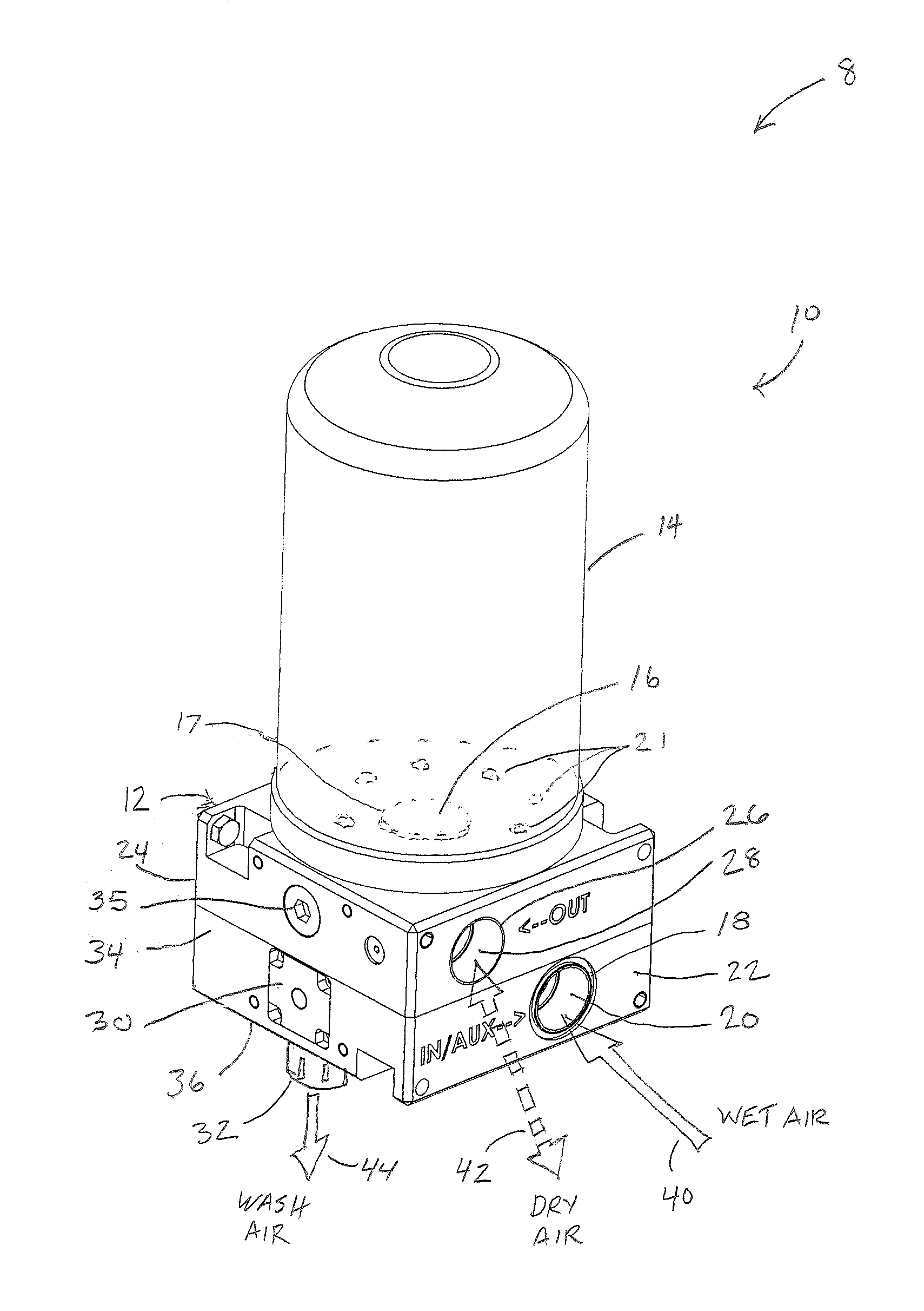
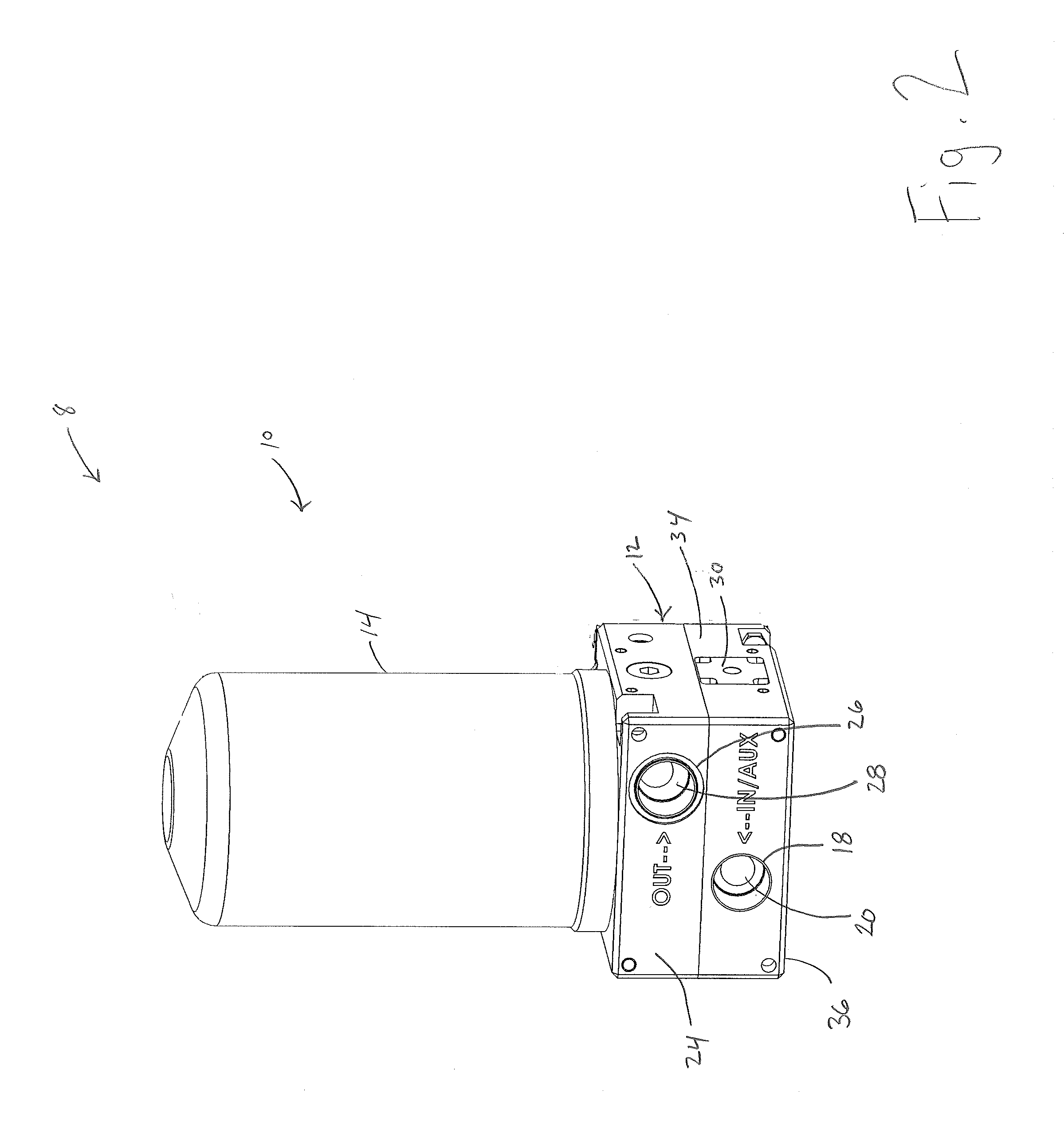
[0016]In the following Detailed Description, reference is made to the accompanying drawings which form a part hereof, and in which is shown by way of illustration specific embodiments in which the invention may be practiced. In this regard, directional terminology, such as “top,”“bottom,”“front,”“back,”“leading,”“trailing,” etc., is used with reference to the orientation of the Figure(s) being described. Because components of embodiments of the present invention can be positioned in a number of different orientations, the directional terminology is used for purposes of illustration and is in no way limiting. It is to be understood that other embodiments may be utilized and structural or logical changes may be made without departing from the scope of the present invention. The following detailed description, therefore, is not to be taken in a limiting sense, and the scope of the present invention is defined by the appended claims.

[0017]FIG. 1 is a perspective view generally illustrat...


PUM


Abstract

A regenerative air drying system including at least one dryer module including a housing having a inlet air passage, an outlet air passage, and a wash air passage. The air dryer system further includes a desiccant canister mounted to the housing and in communication with the inlet, outlet, and exhaust air passages, and a single controllable valve selectively moveable between a first position and a second position, wherein the single controllable valve, when in the first position, forms a supply air flow path from the inlet air passage, through the desiccant canister in a first direction, and to the outlet air passage, and when in the second position, forms a wash air path from the outlet air passage, through the desiccant canister in a direction opposite the first direction, and to the exhaust air passage.

Description

CROSS-REFERENCE TO RELATED APPLICATION[0001]This Non-Provisional Application claims benefit to Provisional Application No. 61 / 583,552, filed Jan. 5, 2012, entitled: Regenerative Air Dryer, which is incorporated herein by reference.BACKGROUND[0002]Compressed air systems are used in a wide variety of applications to power a wide variety of devices, such as spray or paint guns in a compressed air painting system, for example. In order to prevent damage to air powered devices, such as through corrosion, for example, or to prevent adversely affecting processes, such as contaminating paint in a spray painting process, for example, the compressed air is dried and other contaminants removed prior to being used.[0003]Air drying systems, including regenerative air drying systems, have been developed for such purposes. Regenerative air drying systems pass air through a desiccant material which removes moisture from the compressed air, with the desiccant material being able to be dried, or rege...

Claims


Application Information

Patent Timeline
Patent Type & Authority Applications(United States)
IPC IPC(8): B01D53/26
CPCB01D53/261B01D53/0415B01D2257/80B01D53/0407B01D2259/40083
Inventor ERICSON, DUSTIN A.BARGER, BRAD
Owner SUBURBAN MFG
Why Eureka
Try Eureka