Test device and control method thereof

Inactive Publication Date: 2014-01-16
SAMSUNG ELECTRONICS CO LTD
View PDF2 Cites 1 Cited by
  • Summary
  • Abstract
  • Description
  • Claims
  • Application Information

AI Technical Summary

Benefits of technology

The patent describes a device that adjusts the exposure level of a light receiving element based on the signal value and a predetermined target value. If the signal value is higher than the target, the controller will decrease the exposure level of the light receiving element. On the other hand, if the signal value is lower than the target and the difference between the two is greater than a predetermined standard value, the controller will increase the light emitted from the light emitting element to decrease the difference below the standard value. Once the difference is below the standard value, the controller will increase the exposure level of the light receiving element. This helps to optimize the device's performance and improve the overall quality of the captured images.

Problems solved by technology

This may lead to variations in assay results and reduce the reliability of such assay results.

Method used


Image

  • Test device and control method thereof
  • Test device and control method thereof
  • Test device and control method thereof

Examples


Embodiment Construction

[0058]Reference will now be made in detail to exemplary embodiments, examples of which are illustrated in the accompanying drawings, wherein like reference numerals refer to like elements throughout.

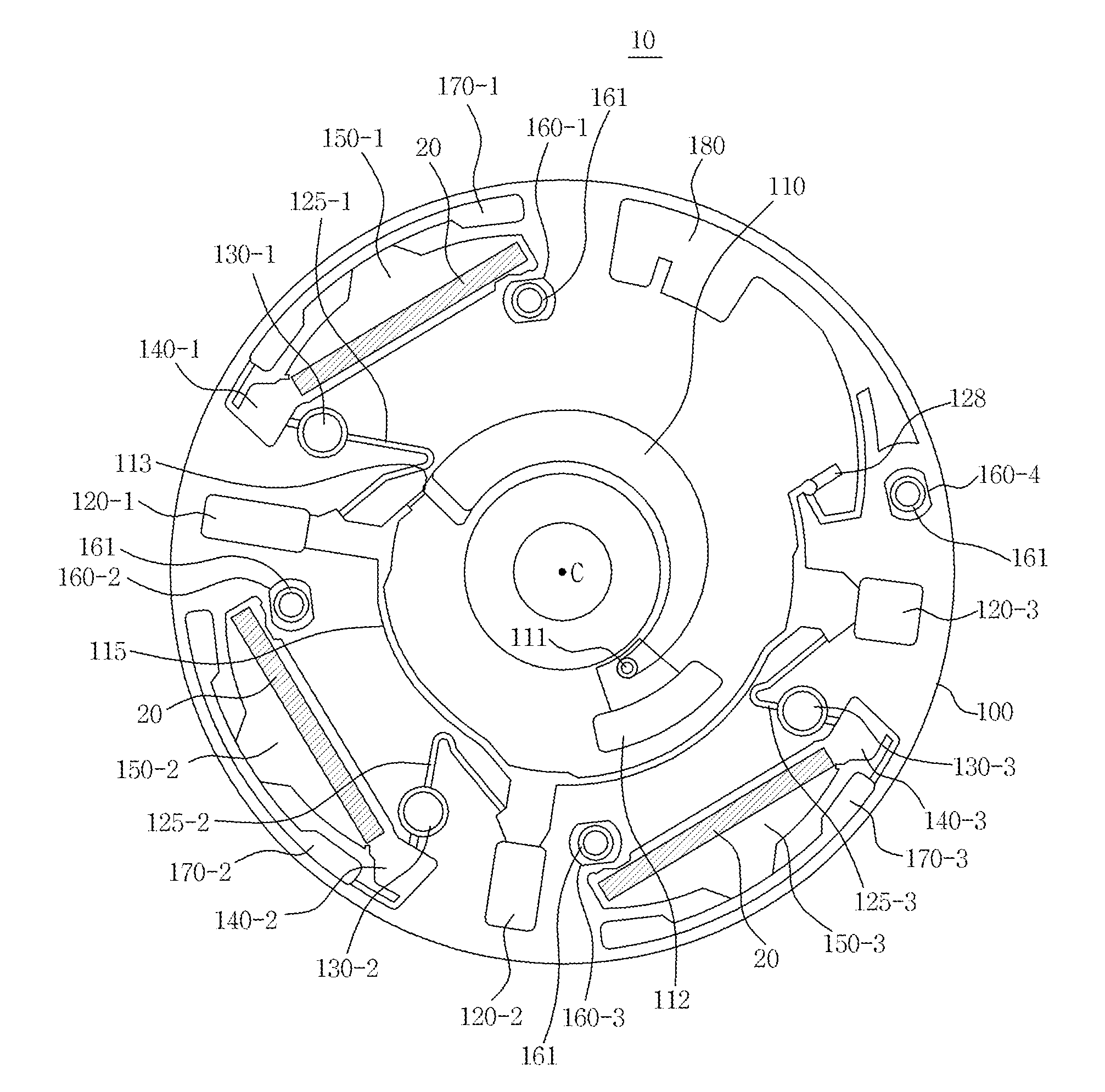
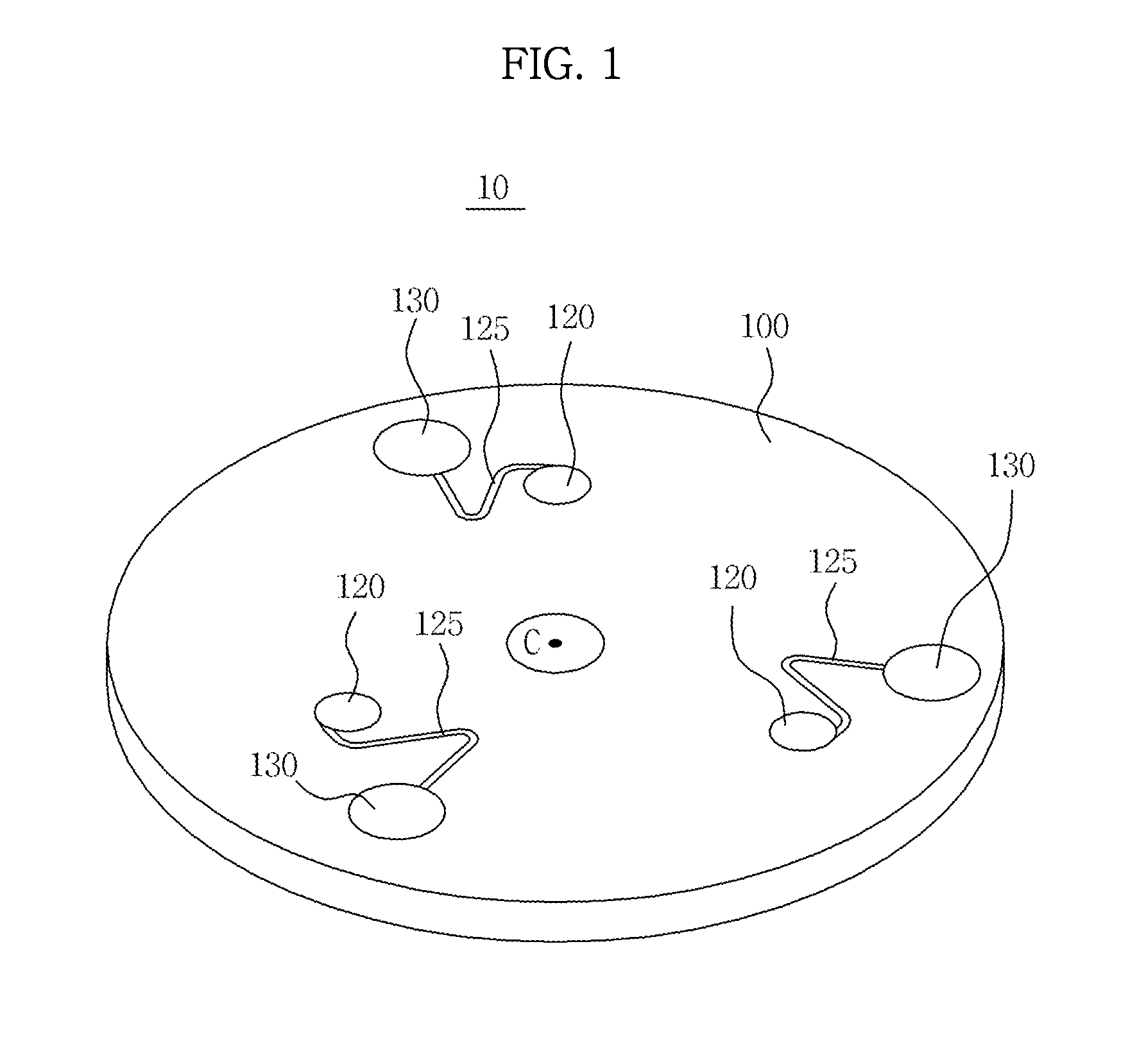
[0059]A microfluidic device according to an exemplary embodiment will be first described, and then a description will be given of a test device, such as a blood testing device, to detect a result of a biochemical reaction occurring on a detection object of the microfluidic device.

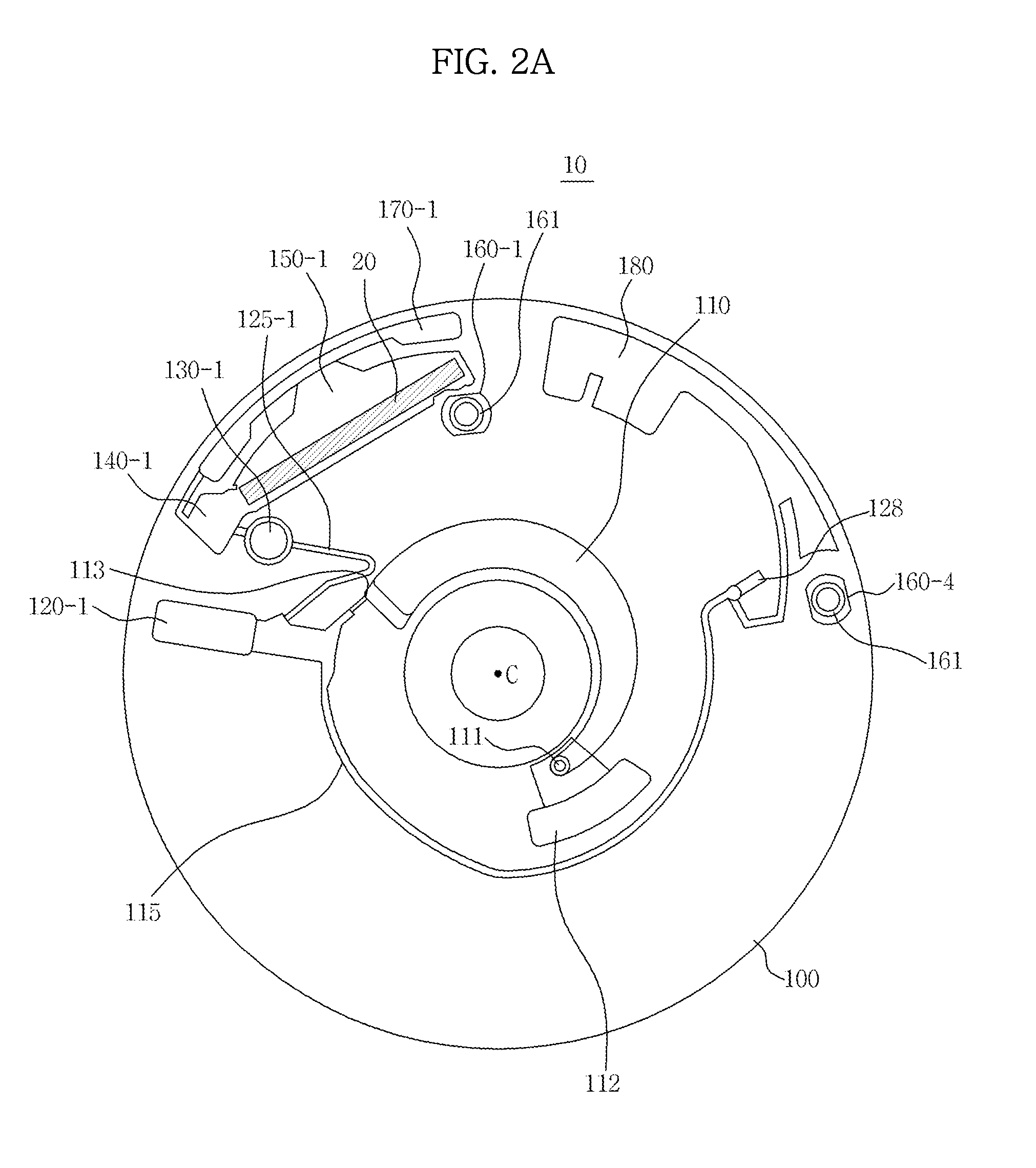
[0060]For the test device, a structure and control method of seating the microfluidic device in the test device will be first described and a detection module to detect the detection object positioned at various radii on the microfluidic device will be described, and finally a description will be given of a method of detecting the detection object while maintaining uniform brightness of the detection object to reduce variation in detection results of the detection object.

[0061]A microfluidic device according to ...


PUM


Abstract

A test device to detect a detection object of a microfluidic device and a control method thereof are provided. The test device includes a light emitting element configured to emit light onto the microfluidic device, a light receiving element configured to capture an image of the detection object through light emitted from the light emitting element, and a controller configured to determine a signal value of a predetermined area of the image of the detection object, and adjust an exposure level of the light receiving element according to a difference between the signal value and a predetermined target value.

Description

CROSS-REFERENCE TO RELATED APPLICATION[0001]This application claims priority from Korean Patent Application No. 10-2012-0075302, filed on Jul. 11, 2012 in the Korean Intellectual Property Office, the disclosure of which is incorporated herein by reference.BACKGROUND[0002]1. Field[0003]Apparatuses and methods consistent with exemplary embodiments relate to a test device to conduct a test for biomolecules using a microfluidic device and a control method thereof.[0004]2. Description of the Related Art[0005]Microfluidic devices are used to perform biological or chemical reactions by manipulating small amounts of fluid.[0006]A microfluidic structure provided in a microfluidic device to perform an independent function generally includes a chamber to accommodate a fluid, a channel allowing the fluid to flow therethrough, and a member (e.g., valve) to regulate the flow of the fluid. The chamber, channel, and valve may be disposed in the platform in a variety of configurations. The microflui...

Claims


Application Information

Patent Timeline
IPC IPC(8): G01N21/17
CPCG01N21/17G01N21/07G01J1/26G01J1/4209B01L3/502715B01L3/50273B01L2200/0605B01L2200/0647B01L2200/141B01L2200/143B01L2200/147B01L2300/069B01L2300/0858B01L2400/0409B01L2400/043B01L2400/0487B01L2400/0688Y10T436/12G01N21/00G01N35/08G01N33/483
Inventor KIM, JONG CHEOL
Owner SAMSUNG ELECTRONICS CO LTD
Why Eureka
Try Eureka