

Glass material for use in press-molding and method of manufacturing optical glass elements
- Summary
- Abstract
- Description
- Claims
- Application Information
AI Technical Summary
Benefits of technology
Problems solved by technology
Method used
Image

Examples
embodiment 1
[0067] Oblate glass preforms of lanthanum-based optical glass M-NbFD13 (made by HOYA (Ltd.)) were placed on a quartz tray and positioned within a bell jar (reaction chamber). The interior of the bell jar was evacuated with a vacuum pump to below 0.5 torr and maintained at 480° C. with heating. While introducing nitrogen gas into the bell jar, evacuation was conducted by the vacuum pump to maintain 160 torr, and after conducting a 30 minute purge, the introduction of nitrogen gas was stopped.
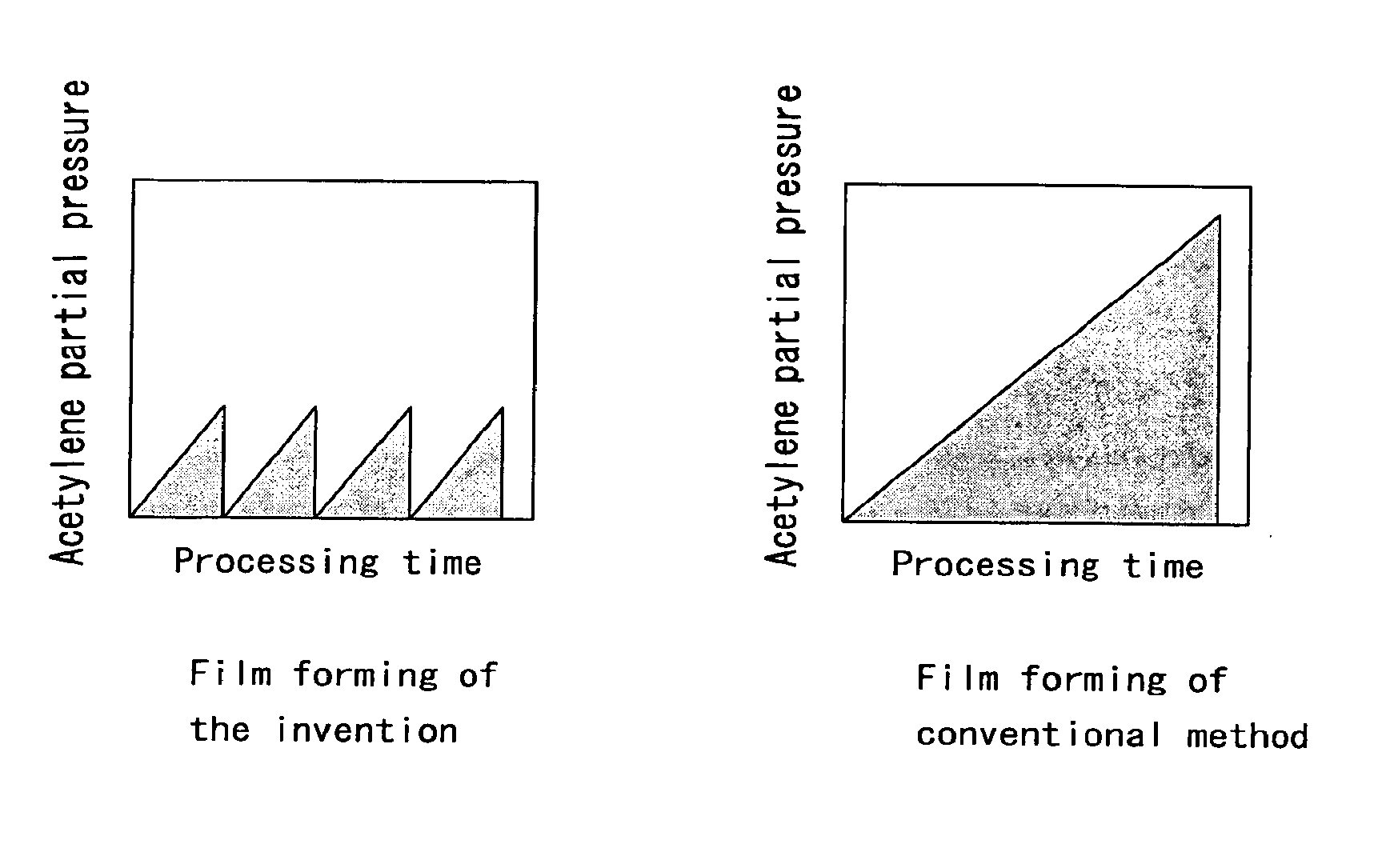
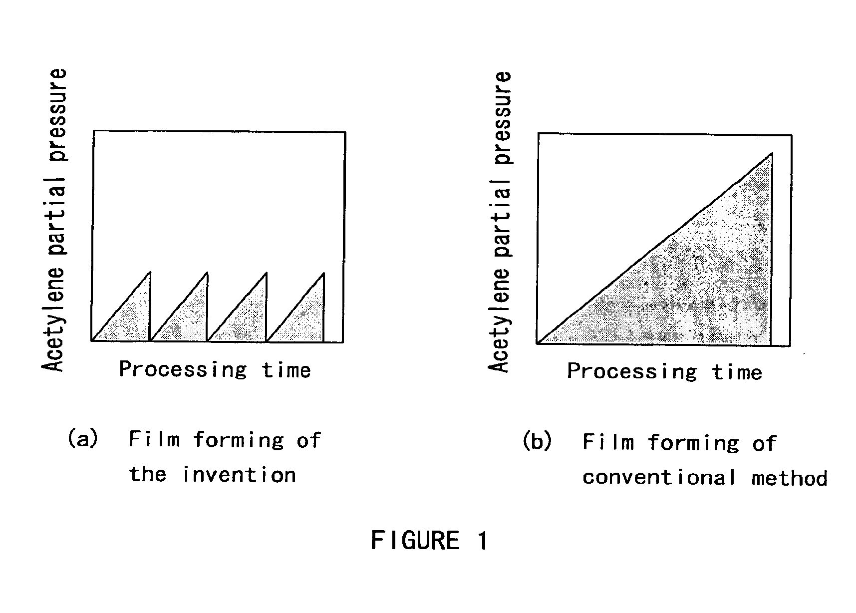
[0068] Next, the interior of the bell jar was evacuated to below 0.5 torr with the vacuum pump, acetylene gas was introduced for 30 minutes at a constant flow rate, and when the pressure within the bell jar reached 30 torr, the introduction of acetylene gas was halted and the interior of the reaction chamber was immediately evacuated by the vacuum pump. When the reaction chamber fell below 0.5 torr (five minutes of evacuation), the introduction of acetylene gas was begun anew.
[0069] This operat...
embodiment 2
[0078] Glass preforms of optical glass (lanthanum based) M-LaC130 (made by HOYA (Ltd.)) were placed on a quartz tray and the tray was positioned on a rack in a bell jar. After evacuating the interior of the bell jar to below 0.5 torr with a vacuum pump, the glass preforms were maintained at 480° C. with heating. While introducing nitrogen gas into the bell jar, evacuation was conducted by the vacuum pump to maintain 160 torr. After conducting a 30 minute purge, the introduction of nitrogen gas has halted.
[0079] After evacuating the interior of the bell jar to below 0.5 torr with the vacuum pump, acetylene gas was introduced into the bell jar. When the pressure within the bell jar reached 30 torr after 30 minutes, the introduction of acetylene gas was halted and the interior of the reaction chamber was immediately evacuated by the vacuum pump. When the interior of the reaction chamber fell below 0.5 torr (five minutes of evacuation), the introduction of acetylene gas was begun anew....
PUM
| Property | Measurement | Unit |
|---|---|---|
| Temperature | aaaaa | aaaaa |
| Partial pressure | aaaaa | aaaaa |
| Partial pressure | aaaaa | aaaaa |
Abstract
Description
Claims
Application Information