Key input device

a key input and input device technology, applied in the direction of contacts, contact surface shape/structure, instruments, etc., can solve the problems of reducing the strength of the hinge portion, difficult to set a reaction force, and difficulty in sufficiently pushing the protruding portion of the click rubber by the key top

Inactive Publication Date: 2014-01-30
ALPS ALPINE CO LTD
View PDF4 Cites 49 Cited by
  • Summary
  • Abstract
  • Description
  • Claims
  • Application Information

AI Technical Summary

Benefits of technology

[0013]A key input device has an input unit disposed on a substrate and a key top for pressing the input unit. Here, a fixed portion fixed to the substrate, a pair of arm portions that are elastically deformable, and the key top supported at the arm portion may be integrally formed, the pair of arm portions may extend along two side portions of the key top facing each other continuously with the fixed portion, a continuing coupling portion may be provided in a direction crossing an extending direction of the arm portion on a top of the arm portion, and at least a part of the coupling portion is connected to a side portion of a front side separated from the fixed portion of the key top.

Problems solved by technology

Therefore, a free length of the hinge portion is significantly reduced, so that it is difficult to set a reaction force when pressing the key top, and the strength of the hinge portion is decreased.
In addition, since the key top is deformed only in a direction in which an edge portion of the free end located away from the inner edge is lowered, it is difficult to sufficiently push the protrusion portion of the click rubber by the key top.
Also, when the key top is pressed in the vicinity of a coupling portion coupled with the hinge portion, it is impossible to lower the key top at a sufficient stroke, and it is further difficult to sufficiently push the protrusion portion.
As a result, it is difficult to densely dispose a plurality of push buttons using a plurality of plate-like elastic members.

Method used


Image

  • Key input device
  • Key input device
  • Key input device

Examples


second embodiment

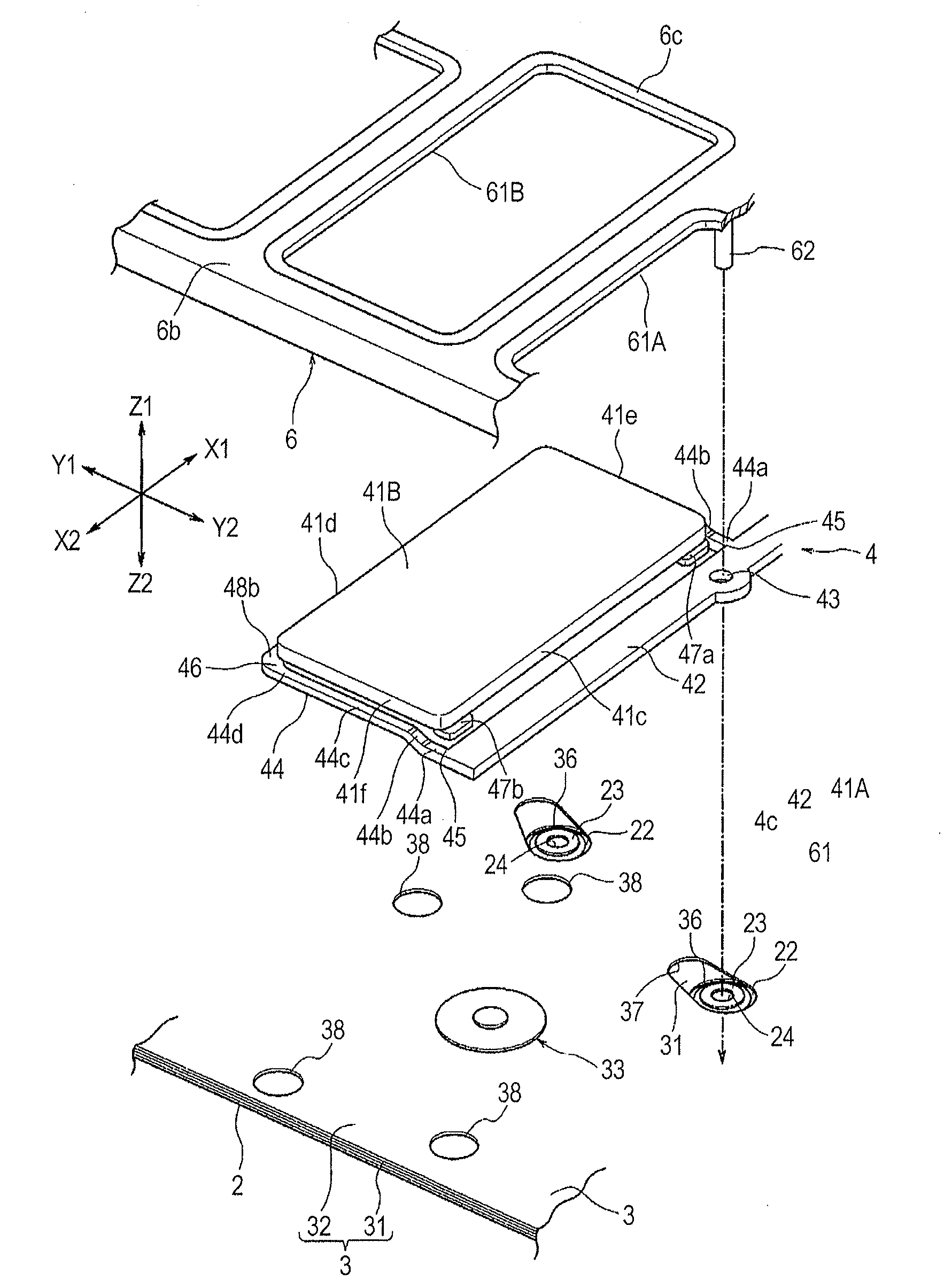
[0091]In FIG. 11, a key input device 201 according to the present invention is shown. In the key input device 201 shown in FIG. 11, a shape of an arm portion 244 that supports the key top 41A and the shape of the arm portion 44 shown in FIG. 4B and the like are different from each other.

[0092]In the arm portion 244 of the key input device 201 according to the second embodiment, a connection portion 245 connected with a fixed portion 242 is positioned downward (Z2 side), a coupling portion 246 connected with the key top 41A is positioned upward (Z1 side) from the connection portion 245, and a deformation portion 244a extending obliquely upward toward the coupling portion 246 from the connecting portion 245 is provided.

[0093]Even in the second embodiment shown in FIG. 11, the key top Al may be positioned upward with respect to the fixed portion 242 when the pressing force does not act, and therefore a large descending stroke of the key top 41A may be ensured.

third embodiment

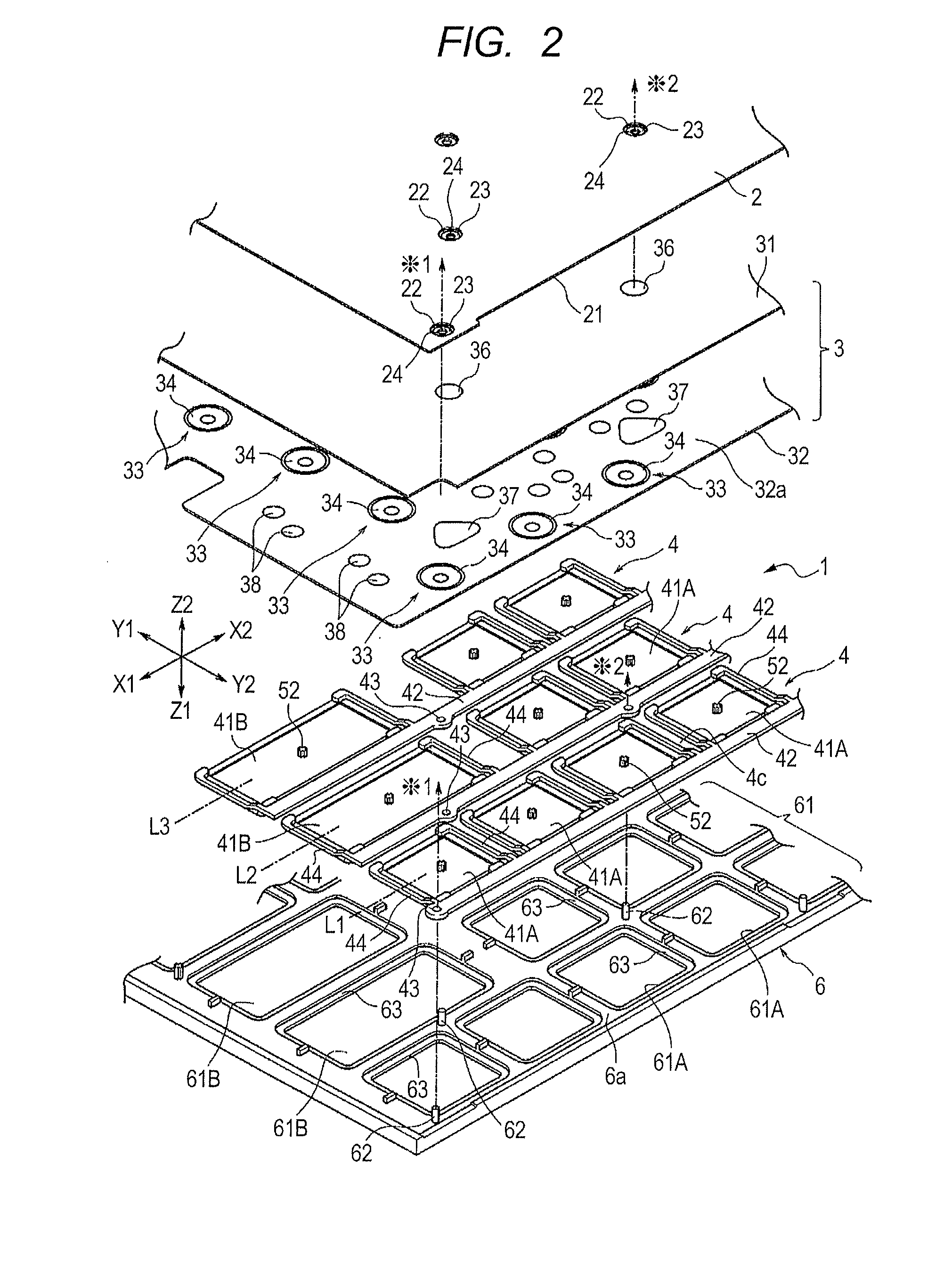
[0094]In FIG. 12, a key input device 301 according to the present invention is shown. FIG. 12 shows the same cross-section as that in FIG. 6. In the key input device 301 shown in FIG. 12, an opening 338 that penetrates both the membrane switch laminated body 31 constituting the sheet laminated body 3 and the spring member holding sheet 32 is formed.

[0095]When the key top 41A is pressed, at least a part of the back abutting portions 47a and 47b and the front abutting portions 48a and 48b may penetrate the entire sheet laminated body 3, and descend up to a position corresponding to the substrate 2. Therefore, even when the key input device 301 is formed in a thin shape, a large descending stroke of the key top 41A may be ensured.

fourth embodiment

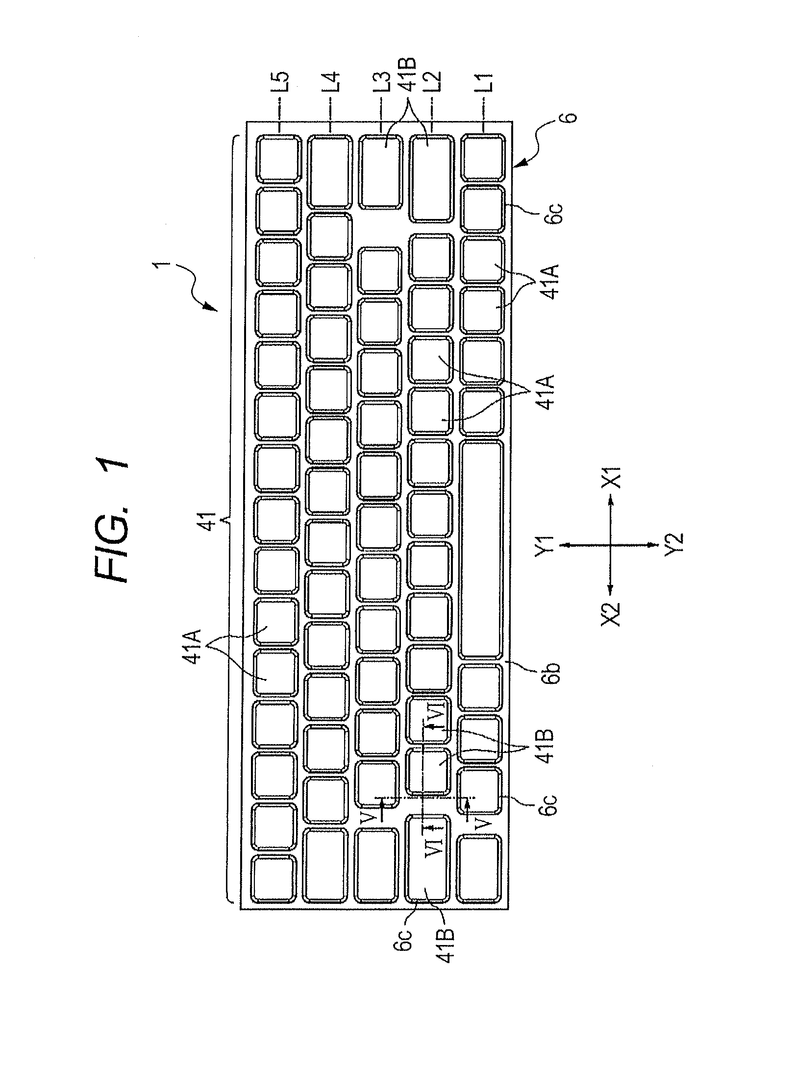
[0096]FIG. 13 shows a plan view of a part of the key input device 401 according to the present invention.

[0097]In the key input device 401, a plurality of key tops 441A and 441B are arranged in parallel in the right and left direction (X1-X2 direction) in a row L1, a plurality of key tops 441C are arranged in parallel in the right and left direction in a row L2. A plurality of key tops 441D are arranged in parallel in the right and left direction in a row L3, and a plurality of key tops 441E are arranged in parallel in the right and left direction in a row L4.

[0098]In the row L1, a fixed portion 442a extending in the right and left direction (X1-X2 direction) is provided. In the row L2, a fixed portion 442b extending in the right and left direction is formed. In the row L3, a fixed portion 442c extending in the right and left direction is formed. In the row L4, a fixed portion 442d extending in the right and left direction is provided.

[0099]The fixed portion 442a of the first row L1...


PUM


Abstract

A tip of a pair of arm portions that integrally extends from a fixed portion and both side portions of a front portion side of a key top are connected with each other in a coupling portion. When a downward pressing force is applied to a center of an operation surface of the key top, a bending moment using a connection portion of a substrate side as a fulcrum and a bending moment using the coupling portion of a tip side as a fulcrum act on the arm portion. The arm portion is deformed into a S-shape having bending deformation portions, and therefore the key top may be lowered in a nearly horizontal posture. The key top has a structure in which both side portions thereof are supported by the arm portions, thereby ensuring a small size and a large elevating stroke.

Description

CLAIM OF PRIORITY[0001]This application claims benefit of Japanese Patent Application No. 2012-165457 filed on Jul. 26, 2012, which is hereby incorporated by reference in its entirety.BACKGROUND[0002]1. Field of the Disclosure[0003]The present disclosure relates to a key input device that inputs an electrical signal by pressing a plurality of key tops or a single key top.[0004]2. Description of the Related Art[0005]Japanese Unexamined Patent Application Publication No. 10-269893 discloses a key input device. In this key input device, a membrane switch sheet having plural groups of electric contacts and a click rubber are overlapped with each other, and a protrusion portion for operating each of the electrical contacts is formed in the click rubber.[0006]A key-top molded body is disposed on the click rubber. A frame portion is provided in the key-top molded body. In the frame portion, a rectangular opening is regularly arranged at a plurality of places, and a rectangular key top is d...

Claims


Application Information

Patent Timeline
Patent Type & Authority Applications(United States)
IPC IPC(8): H01H13/14
CPCH01H13/14H01H13/705G06F3/0202H01H2227/028H01H2227/032H01H2227/036H01H2235/006H01H2235/028H01H2237/004
Inventor KAWANA, YUZURASASAKI, TAKASHISATO, WATARUKURECHI, JUNICHI
Owner ALPS ALPINE CO LTD
Why Eureka
Try Eureka