
Clip

a clip and clip technology, applied in the field of clips, can solve problems such as difficulty in visually confirming whether the hook portion is properly hooked to the wire, and achieve the effect of reducing the difficulty of visual confirmation

Inactive Publication Date: 2014-02-13
TOYOTA BOSHOKU KK
View PDF2 Cites 14 Cited by
  • Summary
  • Abstract
  • Description
  • Claims
  • Application Information

AI Technical Summary

Benefits of technology

The invention provides a clip that makes it easier to visually confirm if a hook portion is hooked onto a target object. The clip has a cover connecting portion, a hook-shaped hook portion that hooks onto the frame structure, and a planar covering portion that is formed in a position facing the back side of the hook portion. An opening is formed in the covering portion that enables the back side of the hook portion to be visible. This allows for easy visual confirmation of whether the hook portion is hooked onto the target object. The clip is designed to avoid interference with the hook and covering portion, and the opening is larger than the hook shape to more appropriately visually confirm if the hook portion is hooked onto the hanging wire.

Problems solved by technology

However, the shape of the hook portion is not in the region (i.e., location) where the through-hole is formed, so it is difficult to visually confirm whether the hook portion is properly hooked onto the wire, from the back side (i.e., the outside) of the hook portion through the through-hole.

Method used


Image

  • Clip
  • Clip
  • Clip

Examples


Embodiment Construction

[0024]Hereinafter, modes for carrying out the invention (i.e., example embodiments) will be described with reference to the accompanying drawings.

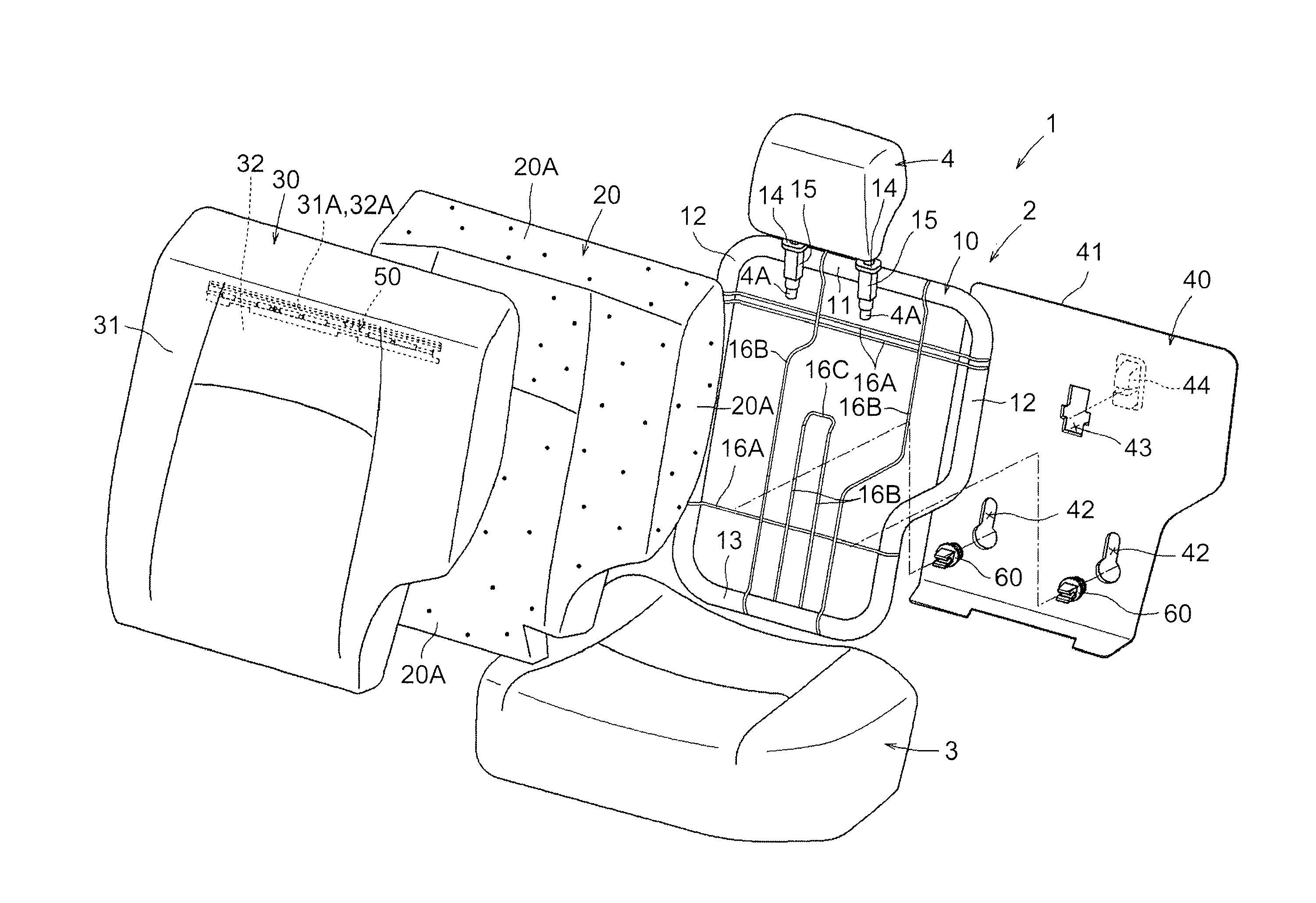
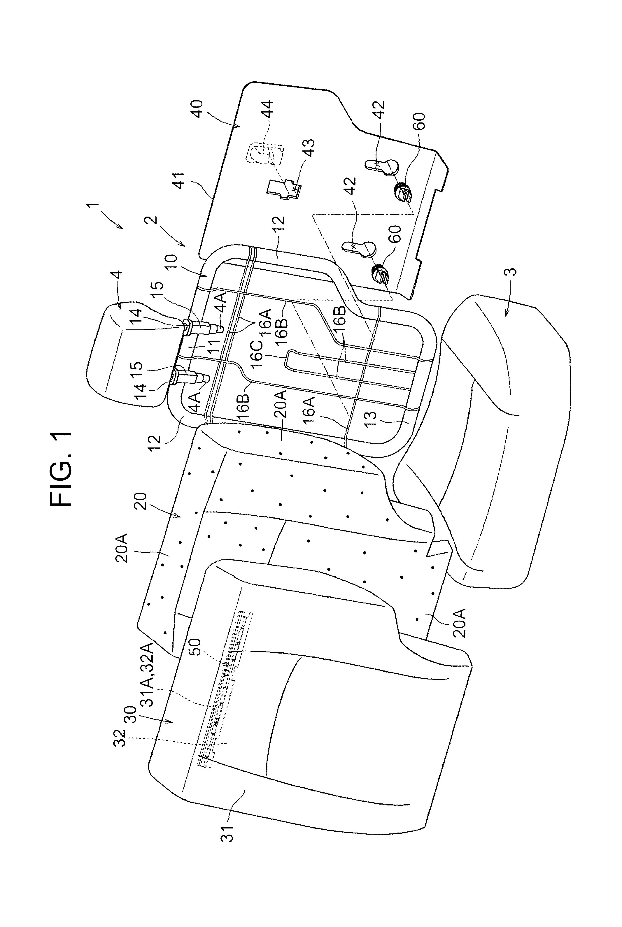
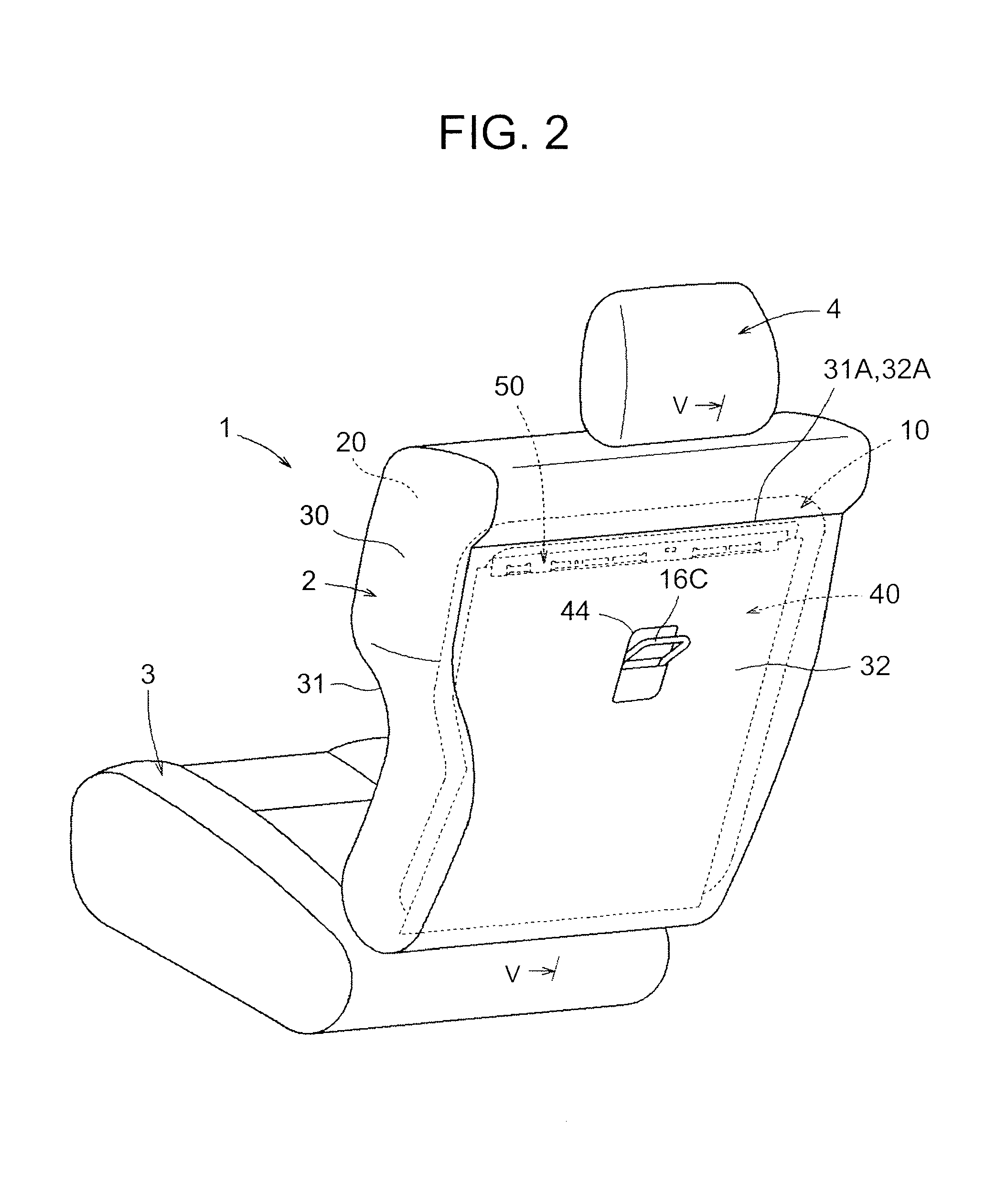
[0025]First, the structure of a clip 50 according to one example embodiment of the invention will be described with reference to FIGS. 1 to 8. As shown in FIG. 1, the clip 50 hooks, and thus fixes, a portion of a cover 30 that covers a surface of a seatback of a vehicle seat 1 to a horizontal wire 16A that is fixed to a back frame 10 that forms a frame of a seatback 2. Here, the vehicle seat 1 is configured as a rear side in a vehicle provided with two rows of seats, and includes the seatback 2 that forms a backrest for a seated occupant, a seat cushion 3 that becomes a seating portion, and a headrest 4.

[0026]The seatback 2 described above is supported by a lower end portion on both left and right sides being connected to a rear end portion of both left and right sides of the seat cushion 3. The seat cushion 3 is supported connected onto t...


PUM


Abstract

A clip that hooks, and thus fixes, a cover of a seat onto a frame structure includes a cover connecting portion that is integrally connected to the cover; a hook-shaped hook portion that hooks onto, and thus fixes to, the frame structure; and a planar covering portion that is formed in a position facing a back side portion of the hook portion. An opening that enables the back side portion of the hook portion to be visible is formed in the covering portion.

Description

INCORPORATION BY REFERENCE[0001]The disclosure of Japanese Patent Application No. 2012-175900 filed on Aug. 8, 2012 including the specification, drawings and abstract is incorporated herein by reference in its entirety.BACKGROUND OF THE INVENTION[0002]1. Field of the Invention[0003]The invention relates to a clip. More particularly, the invention relates to a clip for hooking, and thus fixing, a cover of a vehicle seat to a frame structure.[0004]2. Description of Related Art[0005]Japanese Patent Application Publication No. 2003-230463 (JP 2003-230463 A) describes technology for fastening a seat cover (i.e., a cover) of a vehicle seat to a seat frame by hooking the cover onto the seat frame using a clip that is attached to an edge portion of the cover. A hook-shaped hook portion for hooking, and thus fixing, the clip to an edge portion of the seat frame or a wire extending across the seat frame is formed on the clip.[0006]With the related art described in JP 2003-230463 A, a through-...

Claims


Application Information

Patent Timeline
IPC IPC(8): A47C7/02
CPCA47C7/02B60N2/5825B60N2/6009B60N2/2809
Inventor KAJIWARA, TAKEHIRO
Owner TOYOTA BOSHOKU KK
Learn More