Applicator

a technology for applying parts and liquids, applied in the field of haircare applicators, can solve the problems of excessive ejection of application liquids at the next use, inconvenience in handling, and difficulty in knowing the presence or absence of liquids, and achieve the effect of high reflection efficiency of incident light, preventing excessive filling of the applying part, and easy visual confirmation

Inactive Publication Date: 2016-03-01
MITSUBISHI PENCIL CO LTD
View PDF49 Cites 13 Cited by
  • Summary
  • Abstract
  • Description
  • Claims
  • Application Information

AI Technical Summary

Benefits of technology

[0070]According to the first invention, the applicator has a liquid absorber impregnated with an application liquid, a jagged indicator portion that varies in reflectance of light depending on the amount of the application liquid in the liquid absorber is formed adjacent to the liquid absorber, and the formed portion of the indicator portion is made visible from the outside so that the amount of the application liquid can be displayed by the reflected light of the indicator portion. Accordingly, the reflectance of light from the indicator portion varies from the unused state to a state after use where the application liquid has decreased, so that it is possible to visually confirm the quantity of the application liquid being fully stored or less stored from the change of the reflected light.
[0071]As the indicator portion, the jagged configuration may be formed in an inclined zigzag pattern. If the jagged configuration is formed in an inclined zigzag pattern, the efficiency of reflection of the incident light is high so that the different in strength of reflected light depending on the presence or absence of the application liquid becomes large, thus making it easy to visually confirm the presence or absence of the application liquid.
[0072]In the present invention, when the applicator is adapted to use a liquid absorber as the applying part and include a pumping mechanism for appropriately supplying the application liquid freely stored in the container body to the applying part by operation of the user, it is possible to prevent excessive filling to the applying part by visual observation of the indicator portion.
[0073]Further, when a liquid absorber impregnated with the application liquid is arranged inside the container body while the indicator portion is placed adjacent to the liquid absorber so as to be visible from the outside to demonstrate the quantity of the application liquid in the container body, the residual quantity of the application liquid in the container body can be visually observed.
[0074]According to the applicator of the second invention, the pumping mechanism includes: a piston part that moves forwards and backwards; a compression room that is a space located in the rear part of the container body and partitioned by the piston part to compress a fixed amount of the application liquid by rearward movement of the piston part; and a path that is a channel for delivering the application liquid in the compression room to the applying part and has an inner volume smaller than that of the compression room. Therefore, when the user holds the applicator with the front side up, by moving the piston part rearward by user's operation it is possible to move the application liquid from the compression room located below to the applying part located on the front side via the path. Accordingly, it is possible to feed the application liquid to the applying part without changing the posture of the applicator every time for turning the position of the applying part. Thus, this configuration is convenient.
[0075]Since a hole that communicates the front side space of the piston part in the container body with the outside air at the position directly under a valve and immediately after release of the valve when the compression room is not compressed by the piston part is provided in the path, the internal pressure of the container is relieved to the outside air from the hole through the path, so that no spouting of the application liquid or the like will not occur. Further, a valve structure that communicates the compression room partitioned by the piston part with the front side space of the piston part in the container body before the start of compression in the compression room by means of the piston part and during a partial interval of the compressing stroke after the start of compression in the compression room and shuts off the interior of the container body during the remaining part of the compression stroke is provided. As a result, the long path, which may take an unsteady state (with liquid or the air) depending the state of storage, can be positively filled with the liquid and then shut off from the container body so that the liquid can be supplied to the applying part, thus making it possible to stabilize the ejection quantity.

Problems solved by technology

However, with the specifications of the conventional applicators, other than the free-liquid type, using a porous material such as a sliver or applying part impregnated with an application liquid, there has been the problem that the porous material dyed with the liquid color is always seen even when no liquid remains, hence it is difficult to know presence or absence of the liquid.
Further, the interior of the container forms a closed space during storage, if the internal pressure of the container becomes higher than the ambient pressure due to the expansion in volume of air inside the container or any other reason, there is a possibility that the application liquid will excessively eject out at a next usage due to different in air pressure.
However, all of the applicators of the above patent documents 2 and 4 to 7 entail inconvenience in handling.
Specifically, in the above Patent Document 4, since the cap part needs to be rotated to attach or detach the comber, it is troublesome because the user needs to handle the applicator while taking care that the hair dye etc. will not adhere to the fingers and for other reasons.
Further, in Patent Document 5, the applying part is difficult to hold, and if the applying part is tried to be taken out by dropping or turning the applicator upside down, there is a fear of the liquid running over.
Therefore, this configuration is suited for aerosol type containers in which a compressed gas is charged like the aforementioned Patent Document 3 but is not suited for push-type or valve type containers in which no compressed gas is filled.
Further, in Patent Document 7, since it is necessary to release a snap fixed part and pull out the comber from the base in order to take the comber off the base, the operator needs to handle the applicator with both hands (while taking care of the front end of the comber that is fully oozed with the liquid, which the operator does not want to touch with fingers), thus this configuration results in inconvenience.
Moreover, in the aforementioned Patent Document 2, similarly to Patent Document 7, it is necessary to handle the applicator with both hands to separate the comber from the main body, this configuration hence entails inconvenience and the fear of soling the hands with the application liquid.
However, when these applicators are used with the comber inclined, only the distal ends of the comb teeth come into contact while the applying part is located away from the scalp, hence causing inconvenience in application performance.
On the contrary, when the comb is arranged close to the applying part, the liquid drips from the applying part to the comb teeth, giving rise to a soiling problem of the comb teeth (comber).

Method used


Image

  • Applicator
  • Applicator
  • Applicator

Examples


first embodiment

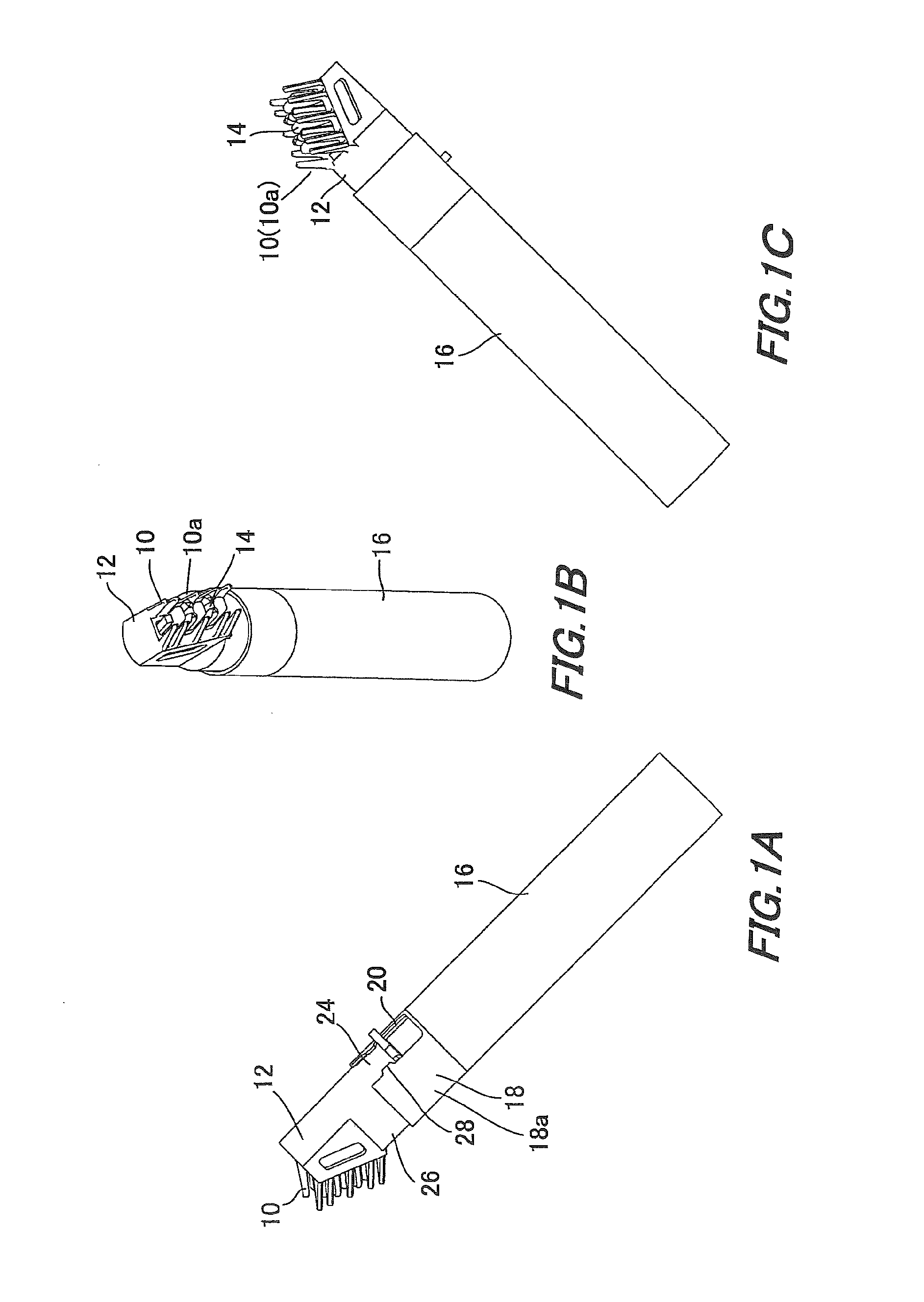
[0145]The comb-toothed parts 10 arranged around opening 12b that is formed by obliquely cutting off front part 12a are formed of multiple (five in the first embodiment) thin strip-like (bar-like) comb-formed projections 10a extending obliquely with respect to the axial direction and arrayed on the left and right sides.

[0146]Front part 12a of comber 12 has a viewing window 12c formed on the flank for permitting a view of the condition of applying part 14. The aforementioned pressing part 24 is formed in rear part 26 of comber 12.

[0147]Comber 12 may be formed of any material as long as it is resinous and can achieve the function as comber 12. Preferably, use of a resin material excellent in water-repellence and cleansability, such as PP (polypropylene) and the like is desired.

[0148][Applying Part 14]

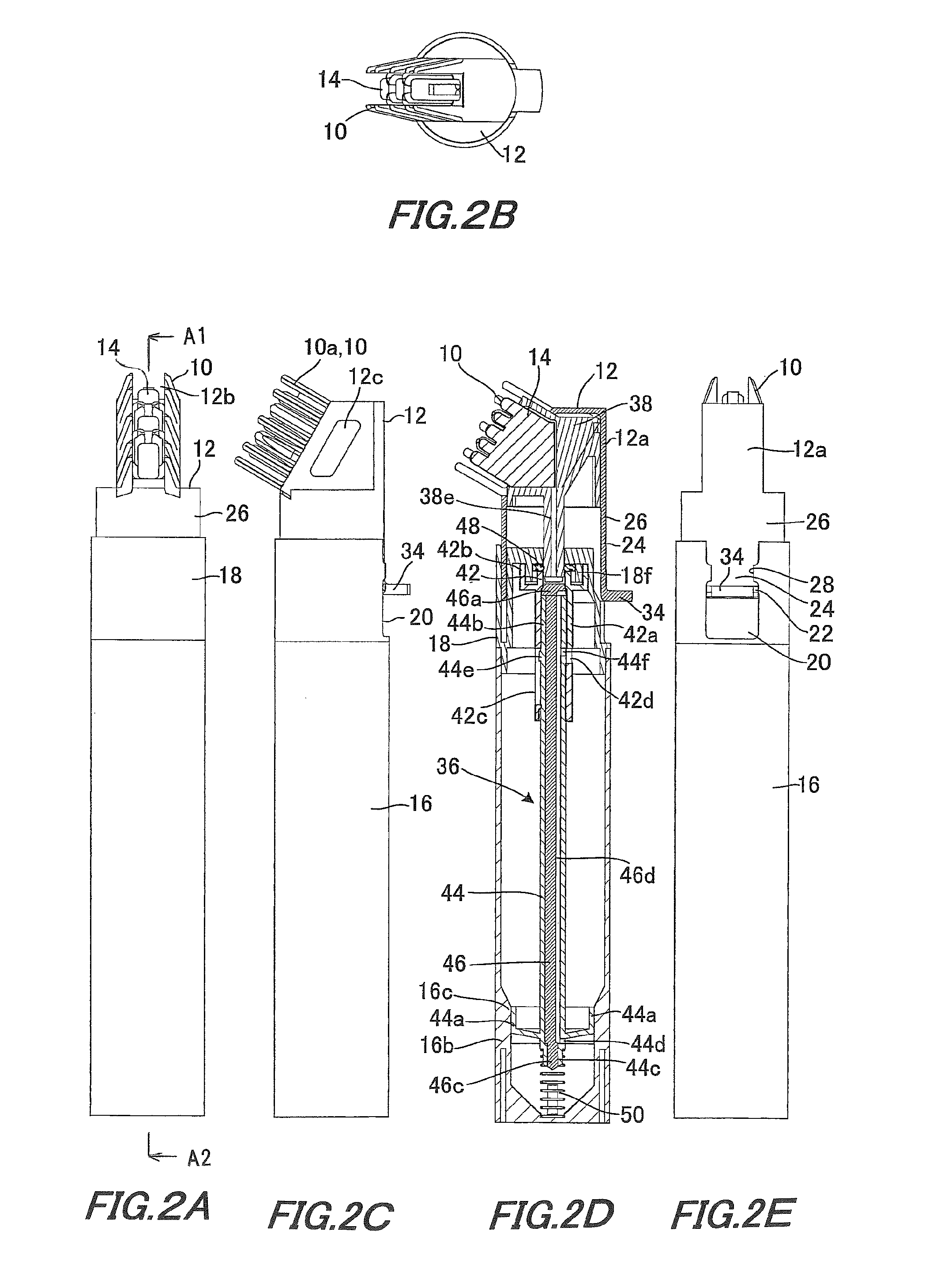
[0149]As shown in FIGS. 1 to 5, applying part 14 is fitted in the interior of comber 12 with its tips exposed between comb-toothed parts 10 and 10. Applying part 14 is configured such that...

third embodiment

[0231]Next, the applicator will be described with reference to FIG. 27.

[0232]In the applicator according to the third embodiment, as shown in FIG. 27 the comber 12 to which applying part 14 is attached has a different configuration from that of the first embodiment. The comber 12 has a pair of left and right comb-toothed parts 10, each having seven comb-formed projections 10a . . . projectively formed long and short in alternate manner. Applying part 14 is formed so that individual pieces are formed wide and narrow in alternate manner.

[0233]Projections 14a . . . of the applying part 14 and comb-formed projections 10a are correspondingly arranged a fixed distance apart.

[0234]Specifically, in the third embodiment, projections 14a . . . of applying part 14 are formed wide, narrow, wide . . . from top to bottom, as shown in FIG. 27. On the other hand, comb-formed projections 10a which are located corresponding to projections 14a are bent outwards so that the distance of each comb-forme...

fourth embodiment

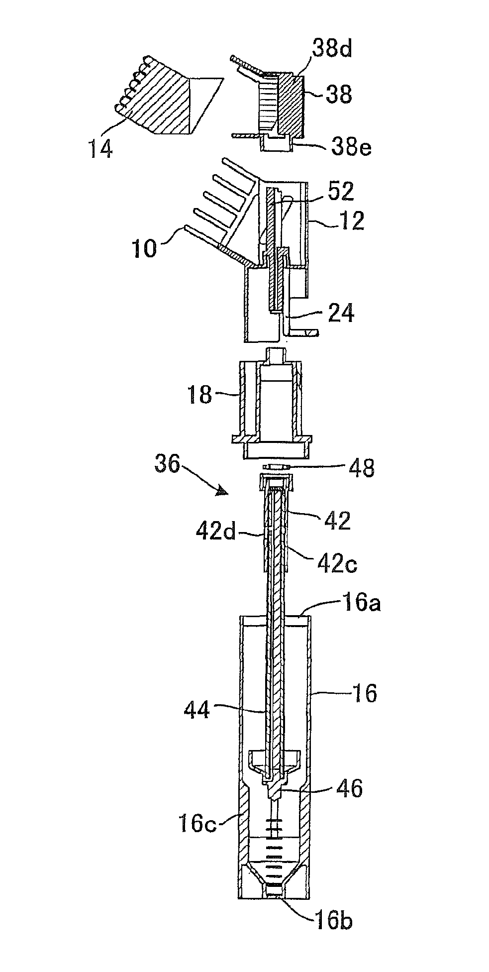
[0237]In the above, as shown in FIGS. 28 to 41, the comber 12 has an angled U-shaped configuration when viewed from the front side with its front side part open. The large applying part 14 assembled with application liquid feeder 38 is adapted to be inserted rearwards from the front opening part of comber 12 so that large-sized applying part 14 can be fitted easily. The structure of applying part 14 of the fourth embodiment is shown in FIG. 35. However, the above-described structures of FIG. 8 and FIG. 31 and others can also be adopted.

[0238](2) In order to fully spread the application liquid over the aforementioned applying part 14, comber 12 is formed with guttered liquid passage portion 52 that opposes and abuts a gutter structure 38d of application liquid feeder 38. Further, pipe portion 38e under application liquid feeder 38 has a cylindrical configuration to which liquid passage portion 52 of comber 12 is inserted.

[0239]Specifically, shown in FIGS. 32 to 33, inside comber 12, ...


PUM


Abstract

An applicator including an applying part of a liquid absorber impregnated with an application liquid. An indicator portion having a jagged configuration that varies in reflectance of light depending on the quantity of the application liquid in the liquid absorber is formed adjacent to the liquid absorber, and the formed area of the indicator portion of an application liquid feeder can be visually observed from the outside so that the quantity of the application liquid can be displayed by the reflected light of indicator portion. The applicator allows a visual check on whether the application liquid is full or less when the applicator is unused or when the application liquid is decreased after use, from the change of the reflectance of light in indicator. The applicator permits easy confirmation of the liquid quantity and can easily avoid liquid blobbing.

Description

TECHNICAL FIELD[0001]The present invention relates to a hair-care applicator, and relates to a hair-care applicator that is attached to a container body to apply an application liquid (hair dye, hair liquid, hair tonic etc.) stored in the container while combing hair (including hairs of humans and others such as pet animals, etc.).BACKGROUND ART[0002]Conventionally there have been known applicators for dyeing hair, which deliver an application liquid such as a hair dye or the like stored in a container, into the spaces between comb teeth of a comber attached to the container to dye hair by combing hair with the comber. The hair-care applicators involve various problems as the following (1) to (4).[0003](1) When the above-described conventional hair-care applicator is used, in order to avoid blobbing of the application liquid or avoid the applicator becoming unusable due to lack of the application liquid in the container, there have been proposals of various methods that enable the u...

Claims


Application Information

Patent Timeline
Patent Type & Authority Patents(United States)
IPC IPC(8): A45D19/00A45D24/24A45D20/24A45D24/22A45D19/02
CPCA45D24/22A45D19/0008A45D19/02A45D24/24A45D19/012A45D19/0066A45D19/026A45D24/28
Inventor NAKASHIMA, ATSUSHI
Owner MITSUBISHI PENCIL CO LTD
Why Eureka
Try Eureka