
Printing method and printing apparatus

a printing apparatus and printing method technology, applied in printing, duplicating/marking methods, other printing apparatus, etc., can solve the problems of increasing the size of the apparatus, increasing the cost, and reducing the possibility of overlooking a printing defect, so as to achieve quick and visual confirmation, quick and intuitively understand the

Active Publication Date: 2019-01-17
SEIKO EPSON CORP
View PDF5 Cites 1 Cited by
  • Summary
  • Abstract
  • Description
  • Claims
  • Application Information

AI Technical Summary

Benefits of technology

The patent text describes a printing method and apparatus that can detect and identify areas of printing defects in a printed image. This allows users to easily see and confirm the presence of printing mistakes, reducing the chance of overlooking them. The method involves detecting a state change in the image while it is being printed and associating this change with a specific position in the image. This can be done by printing the state change information onto the medium in a way that it is easily identifiable, such as a text or a visual identifier. This improved method of identifying printing defects makes it easier for users to take corrective action and ensures consistent quality in the finished printed material.

Problems solved by technology

However, with the method in which the user visually confirms the entire area of the printed material, the confirmation takes time, and it is easy to overlook printing defects when there is a large area to be confirmed.
Although a method in which an image of the printed material is captured by an imaging device and printing defects are detected by comparing the image data with print data is conceivable, doing so may increase the size of the apparatus and increase costs.
As a result, there is an even lower possibility that a printing defect will be overlooked.

Method used


Image

  • Printing method and printing apparatus
  • Printing method and printing apparatus
  • Printing method and printing apparatus

Examples


modified example 1

[0080]FIG. 7B illustrates another example of a printed result of the state change information. The printed result illustrated in FIG. 7B is generated through processing based on the flowchart of FIG. 6A, in the same manner as the printed result illustrated in FIG. 7A. However, at the printing of the state change information in step S08, the state change information is printed as an event mark 78, and text information is not printed. The event mark 78 is printed in the margin to the side of the image each time a state change is detected, and thus the user can know the position of the state change in the printed image with certainty. Accordingly, the user can take particular care to confirm the printed material at the position where the event mark 78 is printed for a printing defect that may have occurred. The possibility that a printing defect will be overlooked is reduced as a result. Furthermore, the text information is not printed, and thus the non-image formation region (the marg...

modified example 2

[0081]FIG. 6B is a flowchart illustrating another example of a printing method according to the disclosure, executed by the computational processing section 42. FIG. 8 illustrates still another example of the printed result of the state change information, and it is a printed result of the state change information processed on the basis of the flowchart in FIG. 6B.

[0082]In FIG. 6B, step S51 to step S53 are the same as step S01 to step S03 in FIG. 6A, and thus these steps will not be described. Upon the flushing operation being executed in step S53, the computational processing section 42 stores the position where the flushing operation have been executed (FP) in the printed image (the printed material) in the memory 43 (step S54), and the process then proceeds to step S55.

[0083]Step S55, which follows step S52 or step S54, is the same as step S05 in FIG. 6A, and thus will not be described. After step S55, the computational processing section 42 confirms whether a detection has been ...


PUM

PropertyMeasurementUnit
Contentaaaaaaaaaa

Abstract

A printing apparatus and a printing method that make it easy to visually confirm whether a printing defect has occurred are provided. A printing method according to an application example includes printing of image in which an image is printed onto a medium by a printing apparatus, detecting of state in which a state change is detected during operations of the printing apparatus in the printing of image, and printing of information in which state change information is printed onto the medium, based on the state change detected in the detecting of state. The state change information is associated with a position in the image where the state change is detected.

Description

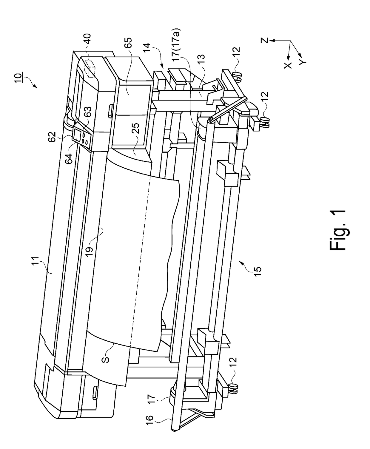
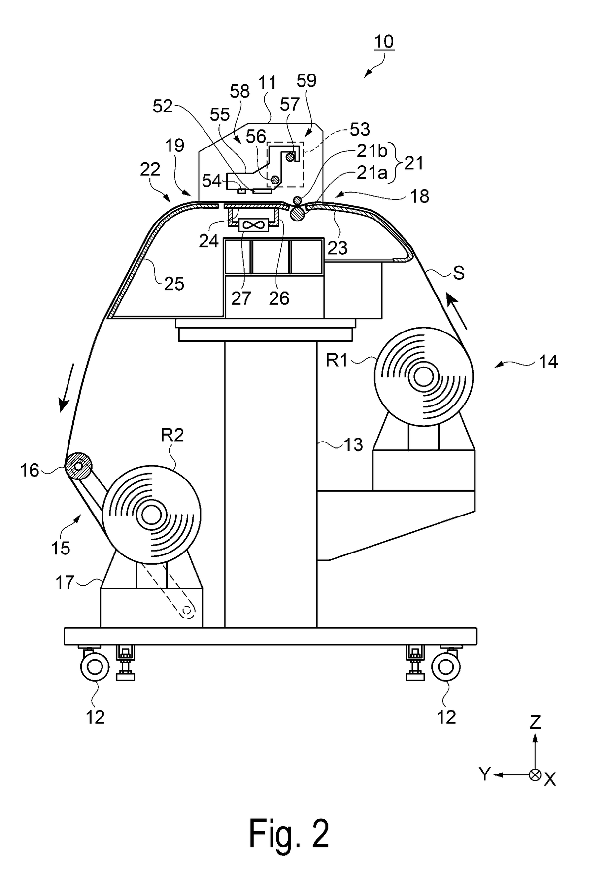
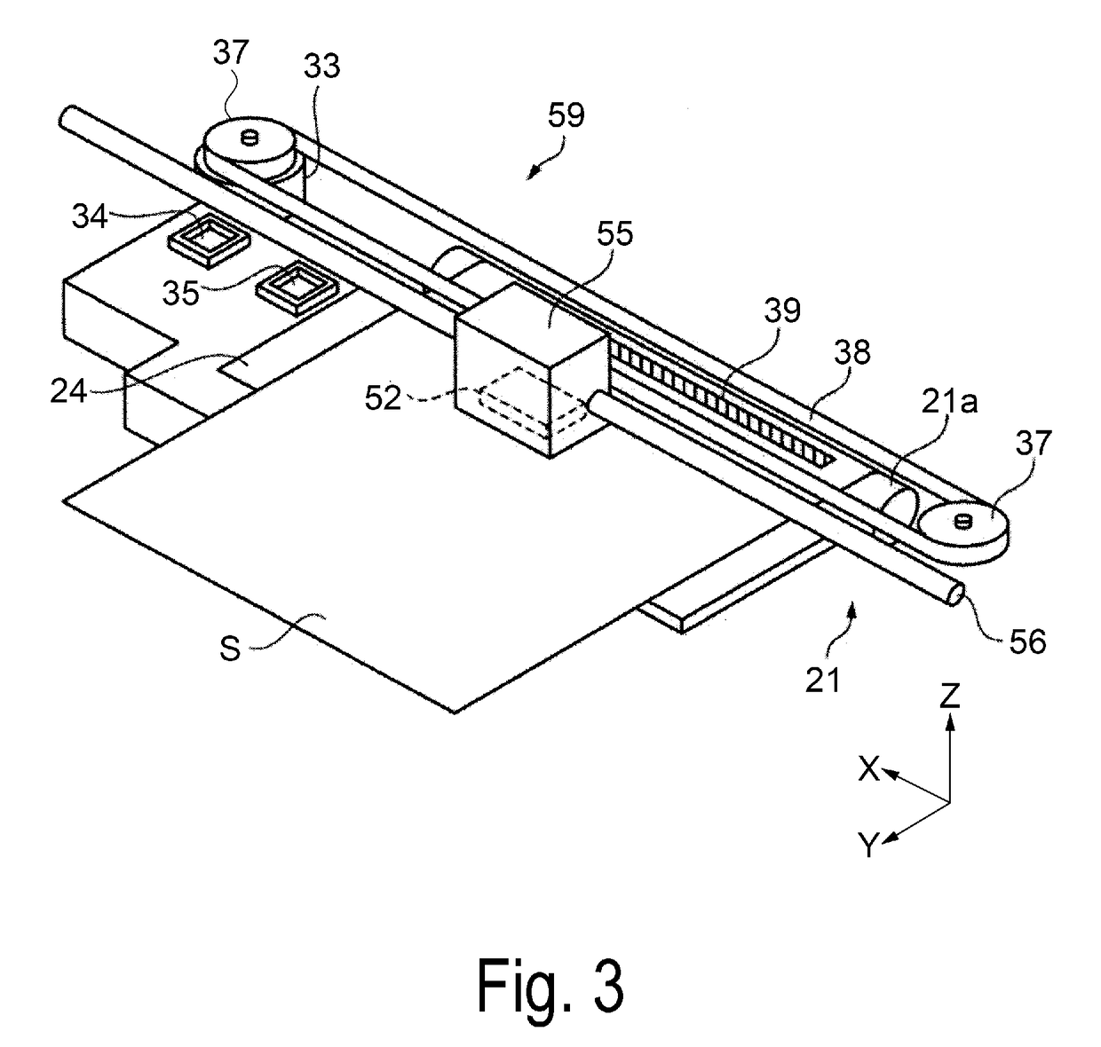
BACKGROUND1. Technical Field[0001]The disclosure relates to a printing method and a printing apparatus.2. Related Art[0002]A printing apparatus that prints an image by ejecting ink droplets onto a medium is known. In such a printing apparatus, it is conceivable to print a pattern for confirming ink droplet ejection errors onto the medium, in cooperation with an error detection operation for detecting whether an ink droplet ejection error has occurred (see JP-A-2016-135557, for example). Through this, a user can confirm and determine whether an ejection error severe enough to impact actual use has occurred.[0003]To determine whether an ejection error severe enough to impact actual use has occurred, it is necessary to confirm whether the printed image indicates a state that will impede actual use. Thus, the user needs to look at the entire range of the printed material and confirm whether there are printing defects.[0004]However, with the method in which the user visually confirms the...

Claims


Application Information

Patent Timeline
IPC IPC(8): B41J2/045
CPCB41J2/04581B41J2/04508B41J2/01B41J29/393B41M5/00B41J2/16517B41J2/16579B41J2/2142
Inventor HATANAKA, YUJINAKAZAWA, YUSUKE
Owner SEIKO EPSON CORP
Learn More