
Measuring apparatus

a technology of measuring apparatus and measuring cylinder, which is applied in the direction of noise figure or signal-to-noise ratio measurement, resistance/reactance/impedence, instruments, etc., can solve the problems of complex operation, inability to separate and measure reactance components, and inability to measure only the purely resistive component as desired, so as to facilitate visual confirmation of impedance and noise current

Active Publication Date: 2013-06-25
HIOKI DENKI KK
View PDF7 Cites 3 Cited by
  • Summary
  • Abstract
  • Description
  • Claims
  • Application Information

AI Technical Summary

Benefits of technology

Enables precise measurement of resistive and reactance components and automatic alternation between impedance and noise current calculations, simplifying the measurement process and improving precision.

Problems solved by technology

This means that although it would be desirable to accurately measure the purely resistive component of the measured resistance, since the resistance value measured by the resistance measuring apparatus described above includes both the purely resistive component of the measured resistance and the reactance component mentioned above, there is the problem that it is not possible to measure only the purely resistive component as desired.
Also, although there are also cases where it is necessary to separate and measure only the reactance component, with the resistance measuring apparatus described above, there is a further problem in that it is not possible to separate and measure the reactance component.
However, in the impedance measuring apparatus (third measuring apparatus) that has already been developed, it is necessary, both when it is desirable to know the noise current during the measuring of resistance and when it is desirable to know the resistance during the measuring of the noise current, to manually switch the measuring mode to the desired measuring mode, resulting in the problem that operation is complex.

Method used


Image

  • Measuring apparatus
  • Measuring apparatus
  • Measuring apparatus

Examples


first embodiment

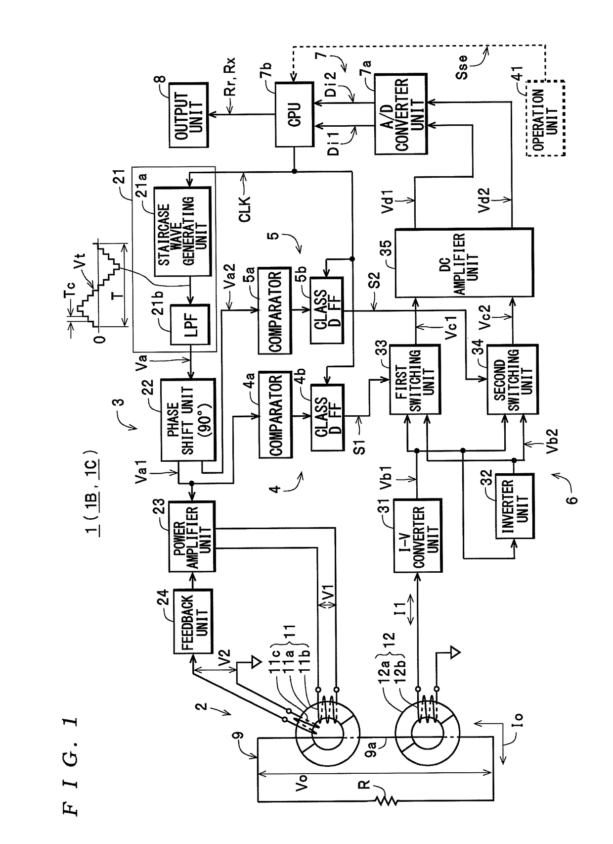
[0063]First, the construction of a measuring apparatus 1 according to the invention will be described with reference to the drawings.

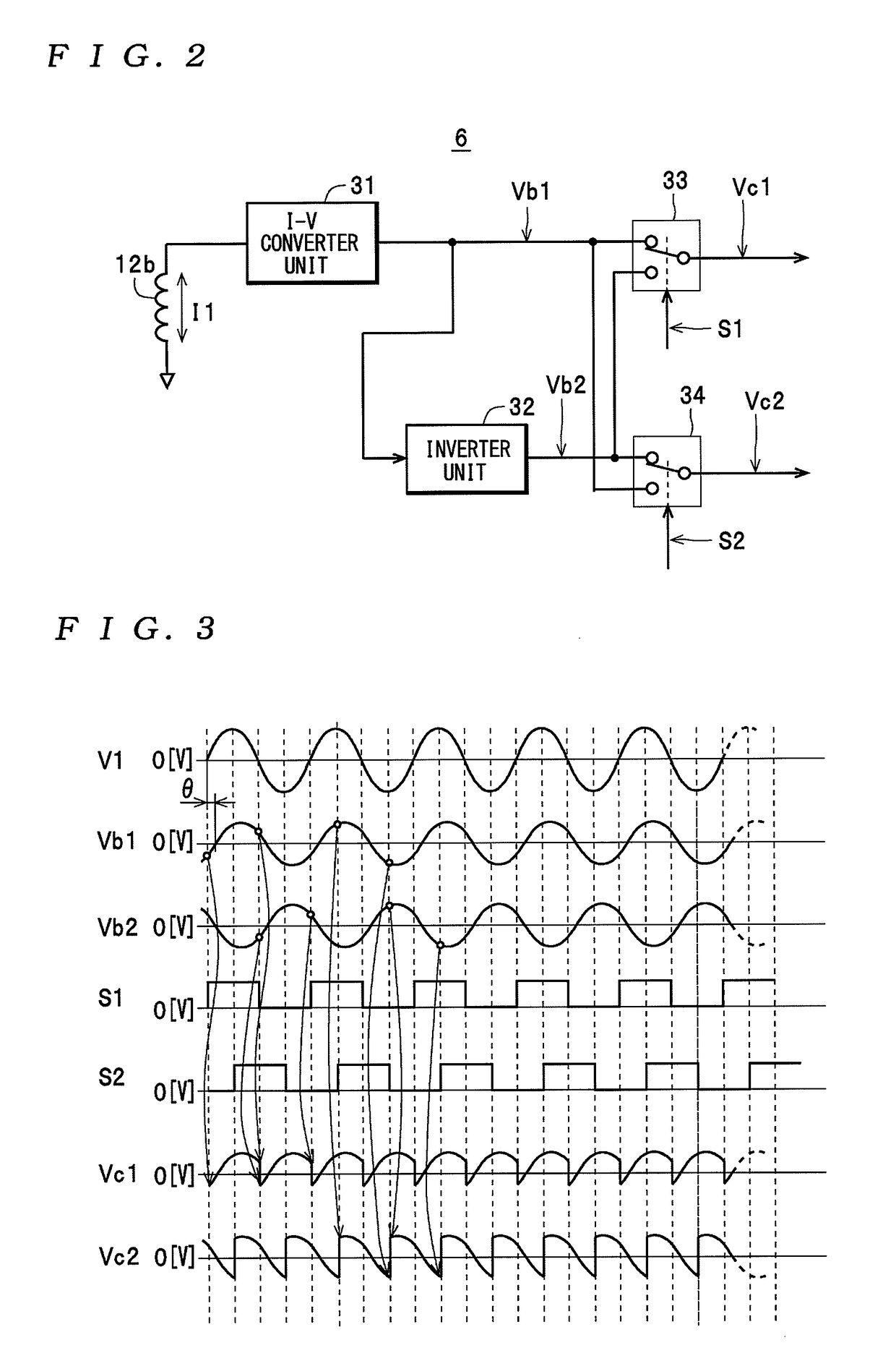
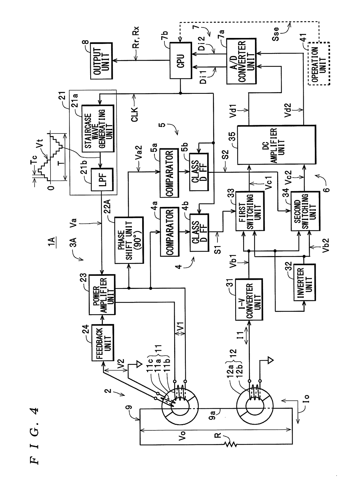
[0064]The measuring apparatus 1 shown in FIG. 1 includes a clamp sensor 2, a voltage injecting unit 3, a first signal generating unit 4, a second signal generating unit 5, a current detecting unit 6, a processing unit 7, and an output unit 8, and is constructed so as to be capable of measuring a purely resistive component Rr and a reactance component Rx of a resistance (loop resistance) R of a measured circuit 9 as measurement values.

[0065]As one example, as shown in FIG. 1, the clamp sensor 2 includes an injection clamp 11 and a detection clamp 12 capable of being attached (clamped) to the measured circuit 9.

[0066]As shown in FIG. 1, the injection clamp 11 includes a ring-shaped core 11a constructed so as to be dividable, and an injection coil 11b (with a known number of turns: N1) and a feedback coil 11c that are wound around the core 11a. The inject...

second embodiment

[0141]Next, the construction of a resistance measuring apparatus 101 that is one example of a measuring apparatus (impedance measuring apparatus) according to the present invention will be described with reference to the drawings.

[0142]The resistance measuring apparatus 101 shown in FIG. 16 includes a clamp unit 102 and an appliance main unit 104 that is connected to the clamp unit 102 via a cable 103, and is constructed so as to be capable of measuring the impedance (as one example in the present embodiment, a resistance value R1 of a resistance (loop resistance) of a measured circuit 105.

[0143]As shown in FIG. 16, the clamp unit 102 includes an injection clamp unit 111, a detection clamp unit 121, and a housing 131. As one example, in the present embodiment, the injection clamp unit 111 includes a first ring-shaped core 112 divided into two, and a first coil 113 (with a known number of turns: N1) wound around the first ring-shaped core 112. The detection clamp unit 121 includes a ...


PUM


Abstract

A measuring apparatus is capable of separately measuring at least one of the purely resistive component and the reactance component of a measured circuit. The measuring apparatus applies an AC voltage to the measured circuit and detects a current flowing in the measured circuit. When doing so, a first detection signal whose amplitude changes in accordance with an amplitude of a real component of the current and a second detection signal whose amplitude changes in accordance with an amplitude of an imaginary component are generated. The at least one of a purely resistive component and a reactance component of the measured circuit is then calculated using the first detection signal and the second detection signal.

Description

BACKGROUND OF THE INVENTION[0001]1. Field of the Invention[0002]The present invention relates to a measuring apparatus that measures the impedance (at least one out of a purely resistive component and a reactance component) of a measured circuit.[0003]2. Description of the Related Art[0004]As one example of this type of measuring apparatus, a resistance measuring apparatus (hereinafter “first measuring apparatus”) disclosed in Patent Document 1 indicated below is known. This resistance measuring apparatus includes an injection transformer that injects, into a measured network (measured circuit), a current with a second frequency that is capable of being discriminated from a current with a first frequency flowing in the measured network, a detection transformer (detection coil) that detects the above two types of current flowing in the measured network, a frequency selecting circuit that takes a second frequency component out of the output of the detection transformer, and a display ...

Claims


Application Information

Patent Timeline
Patent Type & Authority Patents(United States)
IPC IPC(8): G01R25/00G01R27/28G06F19/00
CPCG01R27/02G01R27/08
Inventor IMAIZUMI, SATOSHIMIYAJIMA, SADANORITAKAHASHI, TOSHIKI
Owner HIOKI DENKI KK
Learn More