Method and system for optimizing communication in leaky wave distributed transceiver environments
Active Publication Date: 2014-02-13
GOLBA LLC
View PDF56 Cites 94 Cited by
Summary
Abstract
Description
Claims
Application Information
AI Technical Summary
This helps you quickly interpret patents by identifying the three key elements:
Problems solved by technology
Method used
Benefits of technology
Benefits of technology
The patent describes a system and method for optimizing communication in environments where signals are leaked and distributed. This technology improves the reliability and performance of communication networks in these environments. The patent outlines the technical effects of this technology, which can be summarized as making it easier to transmit signals in unreliable environments.
Problems solved by technology
However, these higher frequencies may experience high propagation loss.
Method used
Image
Click on the blue label to locate the original text in one second.
Reading with bidirectional positioning of images and text.
Examples
Embodiment Construction
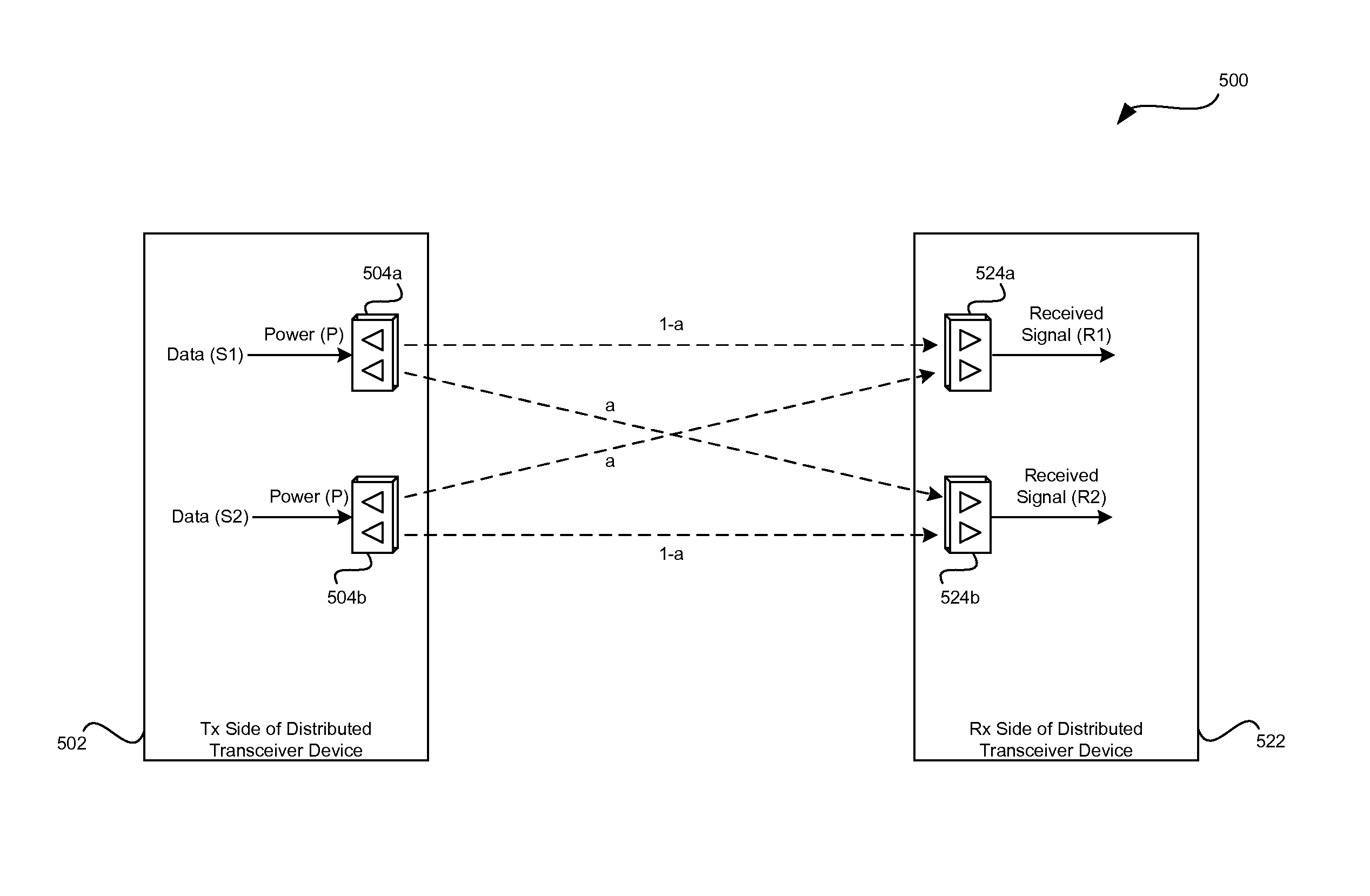
[0047]Certain embodiments of the invention may be found in a method and system for optimizing communication in leaky wave distributed transceiver environments. In various exemplary aspects of the invention, a communication device may comprise a plurality of distributed transceivers and one or more corresponding antenna arrays. A processor such as a central processor, a network management engine and / or a coordinate entity may be operable to configure a first distributed transceiver of the plurality of distributed transceivers to receive signals comprising one or more first data streams via one or more first communication links. The processor may be operable to configure a second distributed transceiver of the plurality of distributed transceivers to receive signals comprising one or more second data streams via one or more second communication links. The processor may be operable to determine a channel response matrix associated with communication of the one or more first data stream...
PUM
Abstract
A communication device may comprise a plurality of distributed transceivers and one or more corresponding antenna arrays. A processor may configure a first distributed transceiver to receive signals comprising one or more first data streams via one or more first communication links. The processor may configure a second distributed transceiver to receive signals comprising one or more second data streams via one or more second communication links. The processor may determine a channel response matrix associated with communication of the one or more first data streams via the one or more first communication links and / or the one or more second data streams via the one or more second communication links. The processor may optimize one or both of link capacity and / or link reliability of the one or more first communication links and / or the one or more second communication links based on the determined channel response matrix.
Description
CROSS-REFERENCE TO RELATED APPLICATIONS / INCORPORATION BY REFERENCE[0001]This application makes reference to, claims priority to and claims the benefit of:[0002]U.S. Provisional Application Ser. No. 61 / 725,005, which was filed on Nov. 11, 2012; and[0003]U.S. Provisional Application Ser. No. 61 / 680,872, which was filed on Aug. 8, 2012.[0004]This application also makes reference to:[0005]U.S. application Ser. No. 13 / 473,096, which was filed on May 16, 2012;[0006]U.S. application Ser. No. 13 / 473,144, which was filed on May 16, 2012;[0007]U.S. application Ser. No. 13 / 473,105, which was filed on May 16, 2012;[0008]U.S. application Ser. No. 13 / 473,160, which was filed on May 16, 2012;[0009]U.S. application Ser. No. 13 / 473,180, which was filed on May 16, 2012;[0010]U.S. application Ser. No. 13 / 473,113, which was filed on May 16, 2012;[0011]U.S. application Ser. No. 13 / 473,083, which was filed on May 16, 2012;[0012]U.S. application Ser. No. ______ (Attorney Docket No. 26536US02), which was f...
Claims
Application Information
Patent Timeline
Application Date:The date an application was filed.
Publication Date:The date a patent or application was officially published.
First Publication Date:The earliest publication date of a patent with the same application number.
Issue Date:Publication date of the patent grant document.
PCT Entry Date:The Entry date of PCT National Phase.
Estimated Expiry Date:The statutory expiry date of a patent right according to the Patent Law, and it is the longest term of protection that the patent right can achieve without the termination of the patent right due to other reasons(Term extension factor has been taken into account ).
Invalid Date:Actual expiry date is based on effective date or publication date of legal transaction data of invalid patent.

