Apparatus and method for detecting error and variation in light-emitting diode lightting

Inactive Publication Date: 2014-02-20
ELECTRONICS & TELECOMM RES INST
View PDF12 Cites 6 Cited by
  • Summary
  • Abstract
  • Description
  • Claims
  • Application Information

AI Technical Summary

Benefits of technology

[0028]The PWM-tail processing unit may extract a tail signal from the PWM-tail signal, and count

Problems solved by technology

The conventional scheme for sensing a failure using a variation in current in an LED lighting apparatus is inefficient in that it does not maximally utilize the advantage of an LED light source, that is, applicable visible-light communication (VLC) that can be applied

Method used


Image

  • Apparatus and method for detecting error and variation in light-emitting diode lightting
  • Apparatus and method for detecting error and variation in light-emitting diode lightting
  • Apparatus and method for detecting error and variation in light-emitting diode lightting

Examples


Embodiment Construction

[0052]The present invention will be described in detail below with reference to the accompanying drawings. Repeated descriptions and descriptions of known functions and configurations which have been deemed to make the gist of the present invention unnecessarily vague will be omitted below. The embodiments of the present invention are intended to fully describe the present invention to a person having ordinary knowledge in the art. Accordingly, the shapes, sizes, etc. of elements in the drawings may be exaggerated to make the description clear.

[0053]Embodiments of the present invention will be described in detail with reference to the accompanying drawings below.

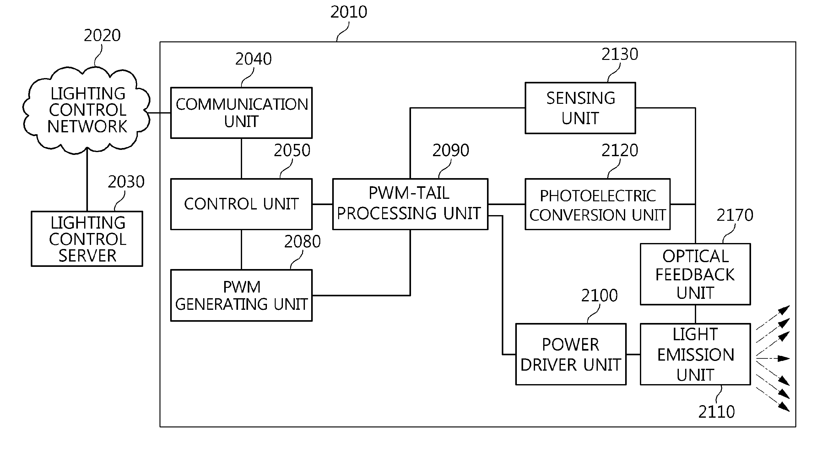
[0054]FIG. 3 is a block diagram showing the configuration of an apparatus for detecting an error and a variation in LED lighting according to an embodiment of the present invention.

[0055]Referring to FIG. 3, an apparatus 2010 for detecting an error and a variation in LED lighting includes a communication unit 2040, a control...


PUM


Abstract

Disclosed herein are an apparatus and method for sensing an error and a variation in Light-Emitting Diode (LED) lighting. In the method, a PWM signal including required light emission information is generated. Tail data including operation information is generated. A CRC value based on the tail data is also generated. A tail-CRC signal is generated by combining the tail data with the CRC value. Finally, a PWM-tail signal is generated by combining the tail-CRC signal with the PWM signal.

Description

CROSS REFERENCE TO RELATED APPLICATION[0001]This application claims the benefit of Korean Patent Application No. 10-2012-0089265, filed on Aug. 16, 2012, which is hereby incorporated by reference in its entirety into this application.BACKGROUND OF THE INVENTION[0002]1. Technical Field[0003]The present invention relates generally to an apparatus and method for detecting an error and a variation in Light-Emitting Diode (LED) lighting and, more particularly, to an apparatus and method that can determine an error and a failure in LED lighting in a lighting apparatus using an LED and can detect a variation in a lighting environment in a lighting area.[0004]2. Description of the Related Art[0005]A conventional technology determines the failure of an LED lighting apparatus by detecting a variation in current in the LED lighting apparatus.[0006]Referring to FIG. 1 illustrating the conventional technology, a lighting apparatus 1010 receives a control instruction from a lighting control serve...

Claims


Application Information

Patent Timeline
IPC IPC(8): G01R31/44
CPCG01R31/44H05B33/0833H05B33/089H05B45/50H05B45/37G01R23/15G01R19/25G01R19/16576G01R29/06
Inventor KIM, YOU-JINKANG, TAE-GYUKIM, DAE-HOKIM, HYUN-SEOKKIM, HYUN-JONGLIM, SANG-KYUJANG, IL-SOONJEONG, JIN-DOOKIM, IN-SUPARK, SEONG-HEE
Owner ELECTRONICS & TELECOMM RES INST
Why Eureka
Try Eureka