Implant system for bone fixation

a technology of implant system and intramedullary nail, which is applied in the field of intramedullary nail, can solve the problems of increasing operation time, cumbersome insertion of relatively small set screw into the shaft of the intramedullary nail, and affecting the insertion of set screw and thread mutual engagement, so as to facilitate the surgical procedure and facilitate the insertion of intramedullary nail within the intramedullary canal of the femur, and achieve high mechanical load stability

Active Publication Date: 2014-02-27
STRYKER EURO OPERATIONS HLDG LLC
View PDF10 Cites 75 Cited by
  • Summary
  • Abstract
  • Description
  • Claims
  • Application Information

AI Technical Summary

Benefits of technology

[0035]When the bore and the one or more guiding structures of the proximal portion of the intramedullary nail are spaced apart from each other, and the coupling unit, for example, in form of a set screw, includes one or more bone fastener engagement members and a drive member with a through hole, wherein the one or more guiding structures slidably receive the one or more bone fastener engagement members, the coupling unit (i.e., the one or more bone fastener engagement members and the drive member) can be preassembled or preloaded within the intramedullary nail, while allowing simultaneous passage of a surgical wire. In pa

Problems solved by technology

In this case, the insertion of the relatively small set screw into the shaft of the intramedullary nail is cumbersome.
Soft tissue overlapping the opening at the proximal end of the nail may hinder the insertion of the set screw and the mutual engagement of the threads.
Thus, the set screw may get stuck within the intramedullary nail and the operation time increases due to addit

Method used


Image

  • Implant system for bone fixation
  • Implant system for bone fixation
  • Implant system for bone fixation

Examples


embodiment 118

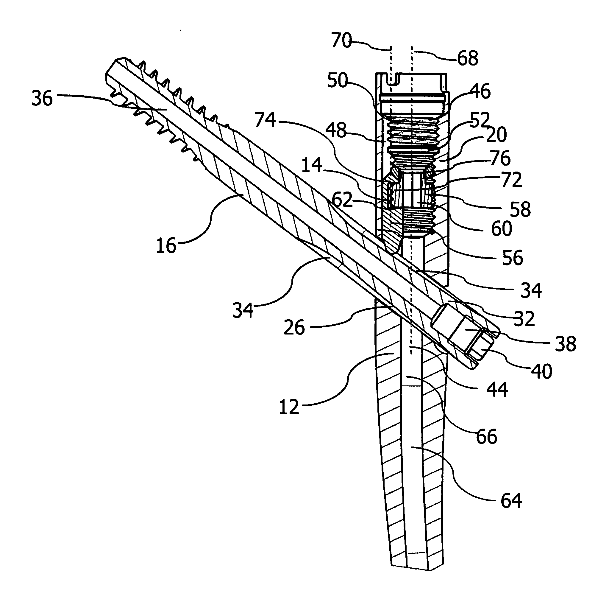
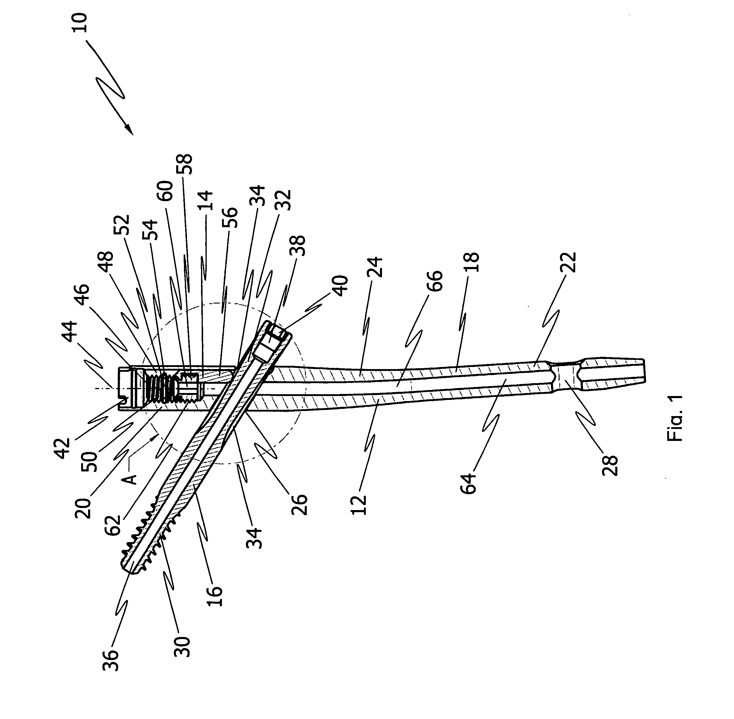
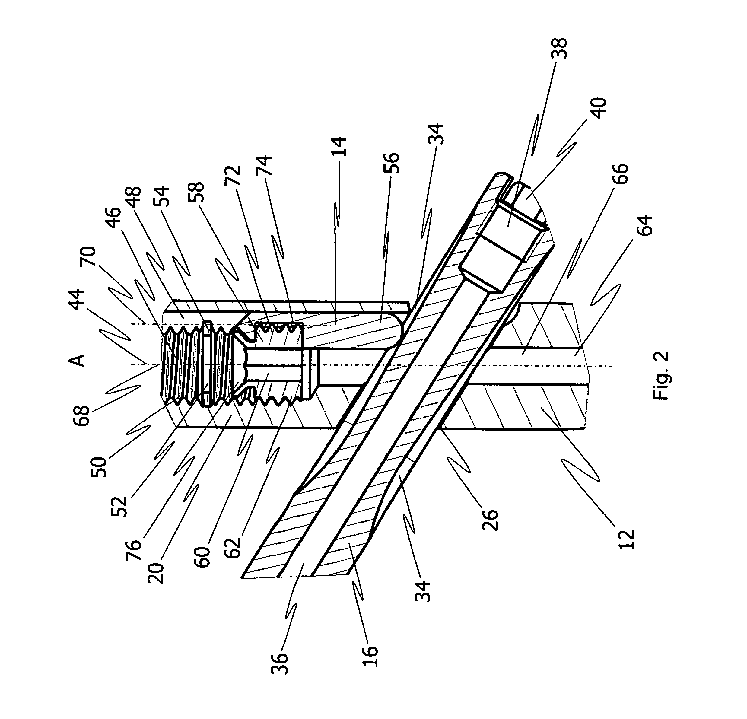
[0090]As shown in FIG. 10, the guiding structures 48 are formed as grooves. One guiding structure 48 is located at the lateral side (right-hand side in FIG. 10) and the other guiding structure 48 is located at the medial side (left-hand side in FIG. 10) of the intramedullary nail 12. Each guiding structure 48 is configured to slidably receive one of the pins 56 of the pin embodiment 118 of the coupling unit 116, such that the pins 56 can engage within the groove 34 of the bone fastener 16 which is configured to penetrate the transverse bore 26 of the intramedullary nail 12. As illustrated in FIG. 10, one pin 56 is arranged at both of the lateral side and the medial side of the intramedullary nail. In other words, one pin 56 is at the lateral side and one pin is at the medial side of the intramedullary nail.

[0091]FIG. 11 illustrates a bottom view a), a side view b), and a top view c) of the alternative pin embodiment 118 used with the drive member 58, which both form the coupling uni...

embodiment 132

[0097]In the present embodiment, the implant system includes an alternative coupling unit embodiment that can be adapted as needed (e.g., in terms of shape, length, width, thickness, etc.) for use in the proximal portion 20 of the intramedullary nail 12 shown in FIG. 12. The alternative coupling unit 130 includes the drive member 58 as shown in and generally described above with reference to FIGS. 1, 2, 8, 9 and 10. The coupling unit 130 further comprises an alternative pin embodiment 132 including two substantially cylindrical pins 56 as generally described above with reference to FIGS. 1, 2, 8, 9 and 10.

[0098]The pin embodiment 132 of the coupling unit 130 has a base member 134 in form of a plate 134 on which the two pins 56 are arranged. In the present embodiment, each pin 56 is integrally formed with the plate 134. Each pin 56 is configured as generally described above with reference to FIGS. 1 and 2. The plate 134 has a circular shape and through hole 136 for receiving a surgic...


PUM


Abstract

An implant system for use in orthopaedic surgery for fixation of bone includes an intramedullary nail and a coupling unit. The intramedullary nail has a medial side, a lateral side and a proximal portion defining a longitudinal axis. The proximal portion includes a bore defining a first axis substantially parallel to the longitudinal axis of the proximal portion and a transverse bore configured to receive a bone fastener. The coupling unit is movably arranged within the bore of the proximal portion and includes one or more bone fastener engagement members at one or both of the lateral side and the medial side of the intramedullary nail.

Description

CROSS-REFERENCE TO RELATED APPLICATIONS[0001]The present application is a national phase entry under U.S.C. §371 of International Application No. PCT / EP2012 / 000577 filed Feb. 8, 2012, published in English, which claims priority from International Application No. PCT / EP2011 / 000585 filed Feb. 8, 2011, all of which are incorporated herein by reference.BACKGROUND OF THE INVENTION[0002]The present disclosure generally relates to an implant system for use in orthopaedic surgery. Specifically, the disclosure relates to an intramedullary nail for internal fixation of bone, such as a femur.[0003]Femur fractures commonly occur in the femoral neck and the trochanteric regions. Typically, trochanteric and sub-trochanteric femur fractures are currently treated with an intramedullary nail having a transverse bore to receive a bone fastener, such as a femoral neck screw usually provided in the form of a lag screw. The intramedullary nail is fitted in the intramedullary canal of the femur and the l...

Claims


Application Information

Patent Timeline
IPC IPC(8): A61B17/72
CPCA61B17/7233A61B17/744A61B17/725
Inventor MUECKTER, HELMUTSTOLTENBERG, INGO
Owner STRYKER EURO OPERATIONS HLDG LLC
Why Eureka
Try Eureka