Implant system for bone fixation

a technology for intramedullary nail and bone fixation, which is applied in the direction of internal osteosynthesis, internal osteosynthesis, osteosynthesis devices, etc., can solve the problems of increasing operation time, potential risks of getting stuck or jamming, and the inability to easily preassemble the intramedullary nail with the main body engagement portion and the drive portion rotatably connected thereto, so as to simplify the surgical procedure and facilitate the implantation of the intramedullary nail within the intramedull

Active Publication Date: 2018-05-31
STRYKER EURO OPERATIONS HLDG LLC
View PDF23 Cites 0 Cited by
  • Summary
  • Abstract
  • Description
  • Claims
  • Application Information

AI Technical Summary

Benefits of technology

[0024]When the coupling member, for example, in form of a set screw, includes a bone fastener engagement portion and a drive portion with a through hole, the coupling member (i.e., the drive portion non-rotatably coupled to the bone fastener engagement portion) can easily be preassembled or preloaded within the intramedullary nail, while allowing simultaneous passage of a surgical wire. In particular, the surgical procedure and the implantation of the intramedullary nail within an intramedullary canal of a femur is simplified and facilitated. Further, due to the one-piece structure of the coupling member, the potential risks of getting stuck or jammed during preassembling into the axial bore of the proximal portion of the intramedullary nail and during sliding of the coupling member within the intramedullary nail toward the bone fastener is significally reduced. Moreover, a specific guiding structure for guiding the bone fastener engagement portion of the set screw within the axial bore of the proximal portion of the intramedullary nail is not necessary.

Problems solved by technology

A set screw having a main body engagement portion and a threaded head drive portion rotatably connected thereto cannot be easily preassembled within the intramedullary nail.
Such a complicated two-piece structure of the set screw allows potential risks of getting stuck or jammed during preassembling into the axial bore of the proximal portion of the intramedullary nail and during sliding of the set screw within the intramedullary nail toward the lag screw penetrating the intramedullary nail.
Thus, the insertion of the relatively small set screw into the shaft of the intramedullary nail is cumbersome and the operation time increases due to additional operation steps.
Moreover, a set screw having one or more prongs or rims cannot prevent an uncontrolled medial deviation of the lag screw.
Hence, the construct of intramedullary nail, set screw and lag screw inserted through the transverse bore of the intramedullary nail and into bone can therefore not provide a high mechanical load stability within the body of the patient.

Method used


Image

  • Implant system for bone fixation
  • Implant system for bone fixation
  • Implant system for bone fixation

Examples


embodiment 10

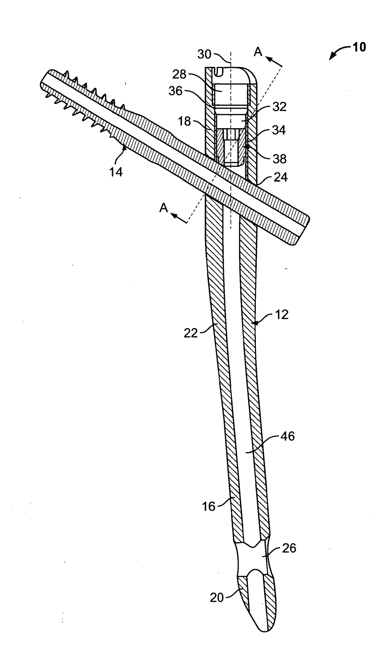
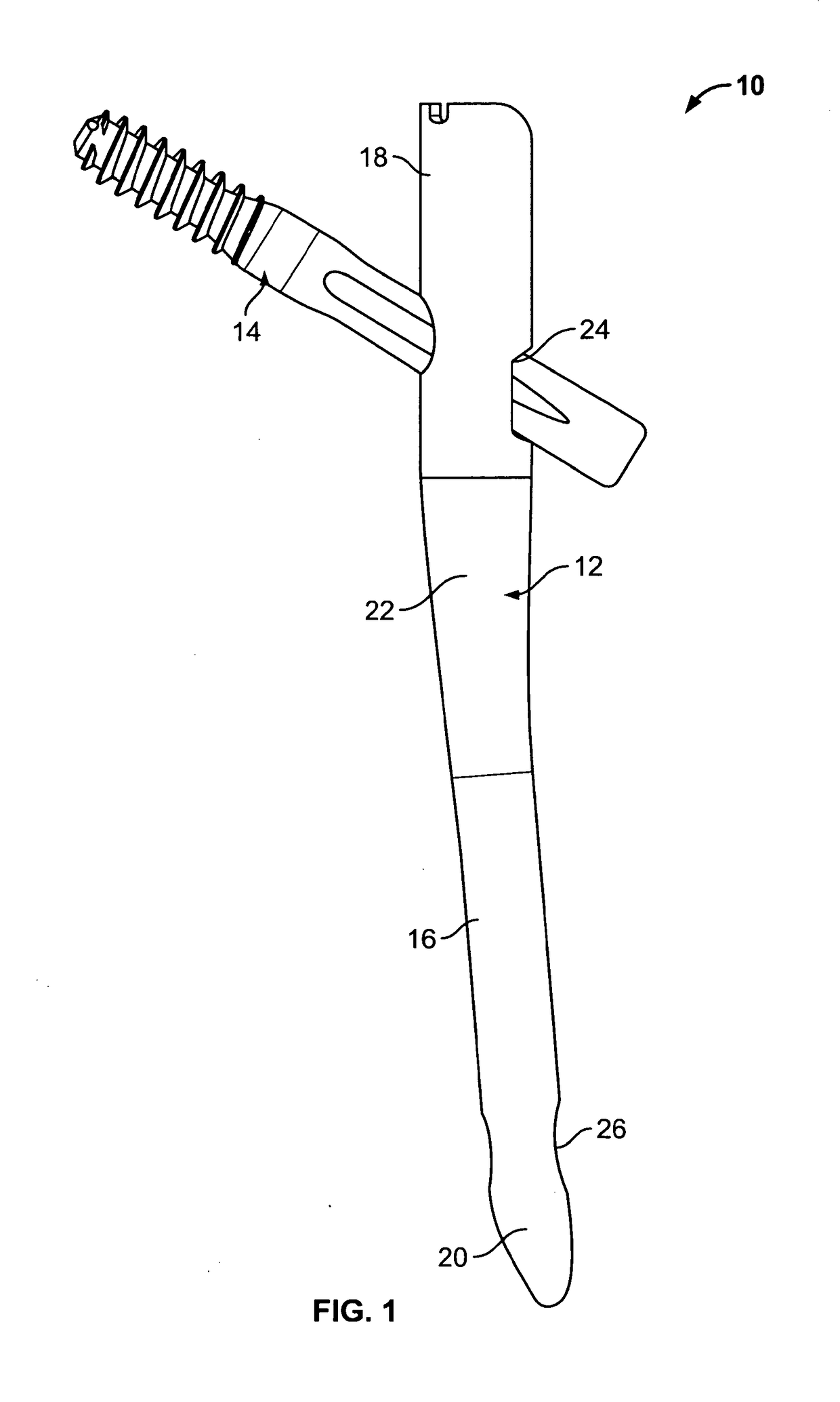
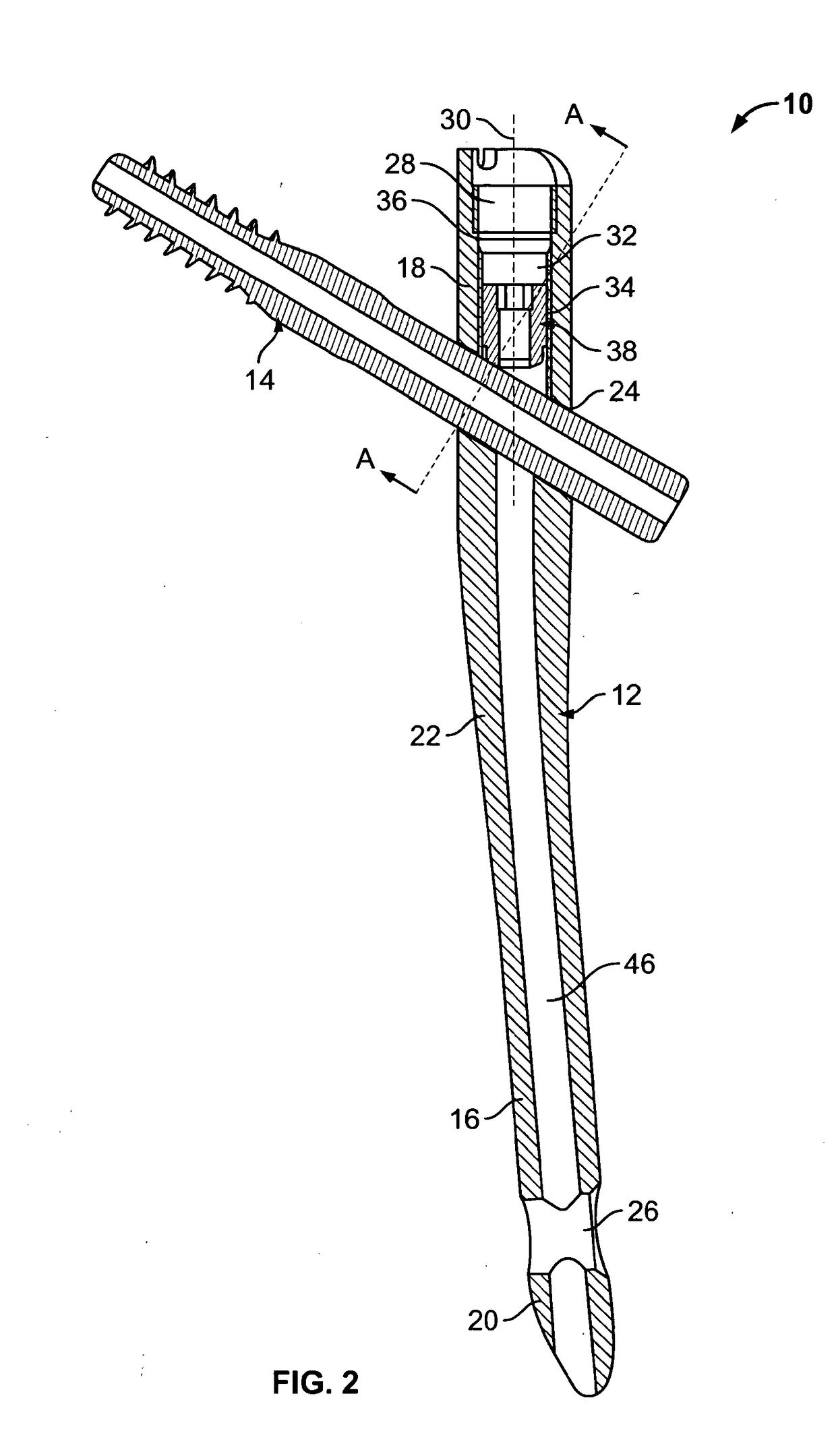
[0036]FIG. 2 illustrates a cross-sectional view of the implant system embodiment 10 shown in FIG. 1. As shown in FIG. 2, the intramedullary nail 12 includes a transverse bore located at the proximal portion 18. An axis of the transverse bore 24 has an angle with respect to a longitudinal axis of the intramedullary nail 12, such that a longitudinal axis of the transverse bore 24 has an oblique extension relative to an axial extension of the proximal portion 18. While in the present embodiment only a single transverse bore 24 is utilized, in other embodiments multiple (e.g., two or more) transverse bores may be provided in the proximal portion 18.

[0037]In the embodiment of the implant system 10 shown in FIG. 2, the bone fastener 14 is a femoral neck screw in the form of a lag screw 14. The lag screw 14 is adapted to penetrate the transverse bore 24 of the intramedullary nail 12.

[0038]The proximal portion 18 of the intramedullary nail 12 has a diameter sufficient to accommodate the tra...

embodiment 14

[0062]The difference between the lag screw embodiment 14 shown in FIG. 7a and that shown in FIG. 7b is that the width w of the at least one groove 54 of the lag screw 14 of FIG. 7a is continuously widening from the shallow end at the rear end of the rear portion 68 to the deeper end at the front end of the rear portion 68. Alternatively, the width w of the at least one groove 54 of the lag screw 14 of FIG. 7b widens from the shallow end into a portion with a constant width w towards the deeper end.

[0063]In an exemplary method for fracture fixation of bone using the above or other implant system embodiments, a guide wire is firstly inserted into a marrow cavity of bone. Then, the cannulated intramedullary nail 12 of the above or other embodiments is inserted over the guide wire into the marrow cavity of bone, i.e., is located in the intramedullary canal of a bone, e.g., the femur. The intramedullary nail 12 comprises the proximal portion 18, the transverse bore 24 and the coupling me...


PUM


Abstract

An implant system for use in orthopaedic surgery for fixation of bone includes an intramedullary nail and a coupling member. The intramedullary nail includes a proximal portion defining a longitudinal axis. The proximal portion includes an axial bore defining an axis substantially parallel to the longitudinal axis of the proximal portion and a transverse bore configured to receive a bone fastener. The coupling member includes a through hole and is movably arranged within the axial bore of the proximal portion. Further, the coupling member includes a drive portion and a bone fastener engagement portion. The drive portion is in one variant non-rotatably coupled to the bone fastener engagement portion. The bone fastener engagement portion is configured to engage the bone fastener penetrating the transverse bore. In one variant the engagement is realized via an extended contact region.

Description

TECHNICAL FIELD[0001]The present disclosure generally relates to an implant system for use in orthopaedic surgery. Specifically, the disclosure relates to an intramedullary nail for internal fixation of bone, such as a femur.BACKGROUND OF THE INVENTION[0002]Femur fractures commonly occur in the femoral neck and the trochanteric regions. Typically, trochanteric and sub-trochanteric femur fractures are currently treated with an intramedullary nail having a transverse bore to receive a bone fastener, such as a femoral neck screw usually provided in the form of a lag screw. The intramedullary nail is fitted in the intramedullary canal of the femur and the lag screw passes through the transverse bore of the intramedullary nail, through the neck of the femur and into the femoral head.[0003]The lag screw is designed to transfer the load of the femoral head into the nail shaft by bridging the fracture line to allow fast and secure fracture healing. Further, the lag screw is allowed to slide...

Claims


Application Information

Patent Timeline
Patent Type & Authority Applications(United States)
IPC IPC(8): A61B17/72A61B17/74A61B17/88
CPCA61B17/7241A61B17/744A61B17/8897A61B17/72
Inventor PRIEN, OLERUMP, MATTHIASKLUEVER, HENDRIK
Owner STRYKER EURO OPERATIONS HLDG LLC
Why Eureka
Try Eureka