

Driving assist system for vehicle
a technology for driving assistance and vehicles, applied in anti-collision systems, external condition input parameters, special data processing applications, etc., can solve problems such as difficulty in reflecting the risk actually perceived by the driver in accelerator reaction force control
- Summary
- Abstract
- Description
- Claims
- Application Information
AI Technical Summary
Benefits of technology
Problems solved by technology
Method used
Image

Examples
first embodiment
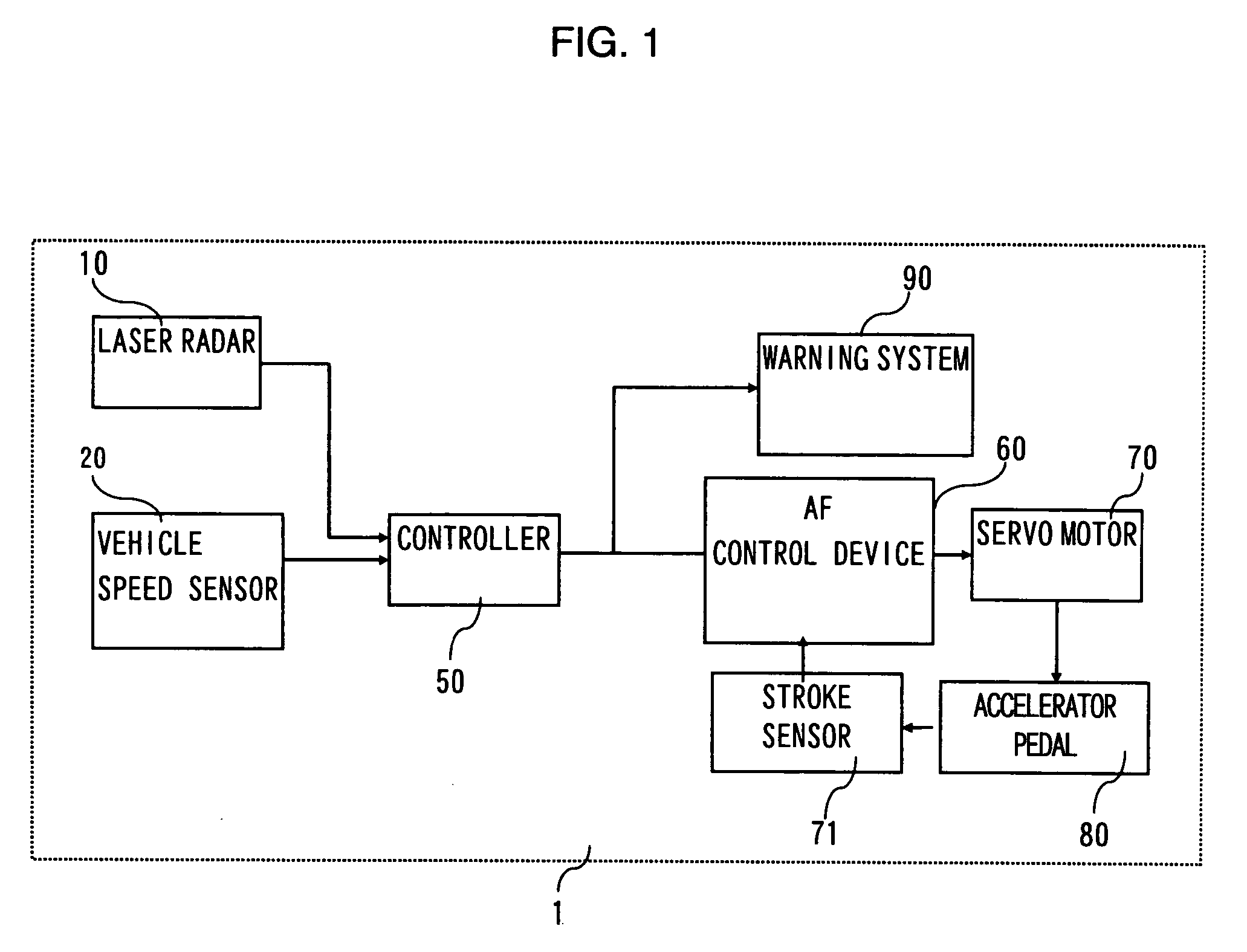
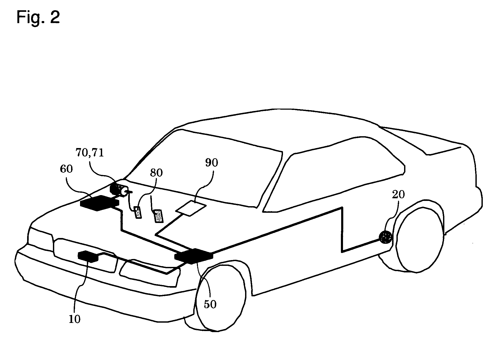
[0018]FIG. 1 shows the structure of a vehicle driving assist system 1 of the first embodiment of the present invention, and FIG. 2 is a structural diagram of a vehicle fitted with the vehicle driving assist system 1.
[0019]First of all, the structure of the vehicle driving assist system will be described.
[0020]A laser radar 10 is attached to a front grill of the vehicle or to a bumper etc., and propagates infrared pulses in a forward horizontal direction for scanning. The laser radar 10 measures reflected radiation of infrared pulses reflected by a plurality of reflecting objects ahead, such as the rear of a vehicle in front, and detects distance (vehicle distance) from the subject vehicle to a preceding vehicle and relative velocity (relative speed) of vehicles based on the elapsed time the reflected radiation to be received. The laser radar 10 outputs the detected vehicle distance and relative speed between vehicles to a controller 50. The laser radar 10 can scan the forward region...
second embodiment
[0060]Next, a method of calculating the risk potential RP of a second embodiment will be described.
[0061]In the second embodiment, in addition to speed adjustment (acceleration or deceleration) of the subject vehicle, speed adjustment of the preceding vehicle is also used to calculate the risk potential RP so that adverse effects on the driver can be reduced even when the preceding vehicle suddenly accelerates or decelerates.
[0062]A risk potential RP2 of the second embodiment is represented by expression 6 below using the base equation P.
RP2=α2×P+β2×P′+γ2×P″ (expression 6)
[0063]Here, α2, β2, and γ2 are constants for respectively applying appropriate weight to P, P′, and P″. P′ and P′ represent once differentiated value and twice differentiated value of the base equation P respectively.
[0064]As shown in expression 6, the risk potential RP2 is obtained from a linear sum of the base equation P, the base equation P differentiated once and the base equation P differentiated twice. If ex...
third embodiment
[0069]A method of calculating the risk potential RP of a third embodiment of the present invention will now be described.
[0070]In the third embodiment, a reciprocal of TTC, Q=1 / TTC is used as a base equation for calculating the risk potential RP. A risk potential RP3 of the third embodiment is represented by the following expression 8 using the base equation Q.
RP3=α3∫Qdt+β3Q (expression 8)
[0071]Here, α3 and β3 are constants for applying a suitable weight to ∫Qdt and Q respectively.
[0072]As shown in expression 8, the risk potential RP3 can be obtained from a linear sum of the base equation Q, and the base equation Q integrated once. If expression 8 is computed using the parameters shown in FIG. 5, it is represented as shown in expression 9 below.
[0073]RP3=C3-α3logd+β3τc(expression9)
[0074]Here, C3 is a constant.
[0075]As shown in expression 9, the risk potential RP3 is calculated using an equation that includes TTC=τc and the vehicle distance d.
[0076]Generally, in a medium to hi...
PUM
 Abstract
Description
Claims
Application Information