

Control Modules for Laser Systems Having Auto-Ranging and Control Capability
a technology of control module and laser system, which is applied in the field of laser control system, can solve the problems of reducing output, affecting human health, and not entirely without risk to human vision, so as to enhance the safety of laser operation, reduce the risk of objects, and improve comparison
- Summary
- Abstract
- Description
- Claims
- Application Information
AI Technical Summary
Benefits of technology
Problems solved by technology
Method used
Image

Examples
Embodiment Construction
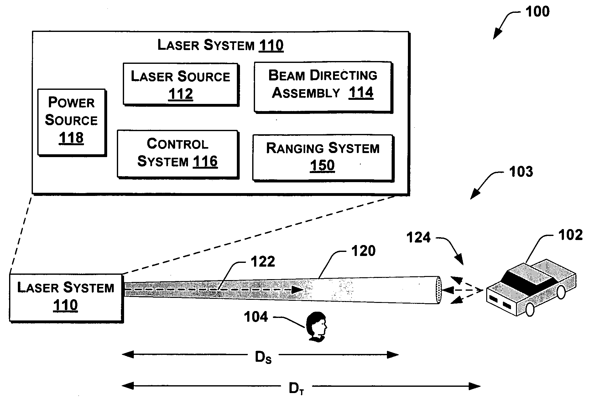
[0019]The present disclosure is directed to laser systems and methods having an ability to automatically adjust a laser output based on a range to an object detected within a field of view. Many specific details of certain embodiments in accordance with the present disclosure are set forth in the following description and in FIGS. 1-11 to provide a thorough understanding of such embodiments. One skilled in the art, however, will understand that the present invention may have additional embodiments, or that the invention may be practiced without several of the details described in the following description.
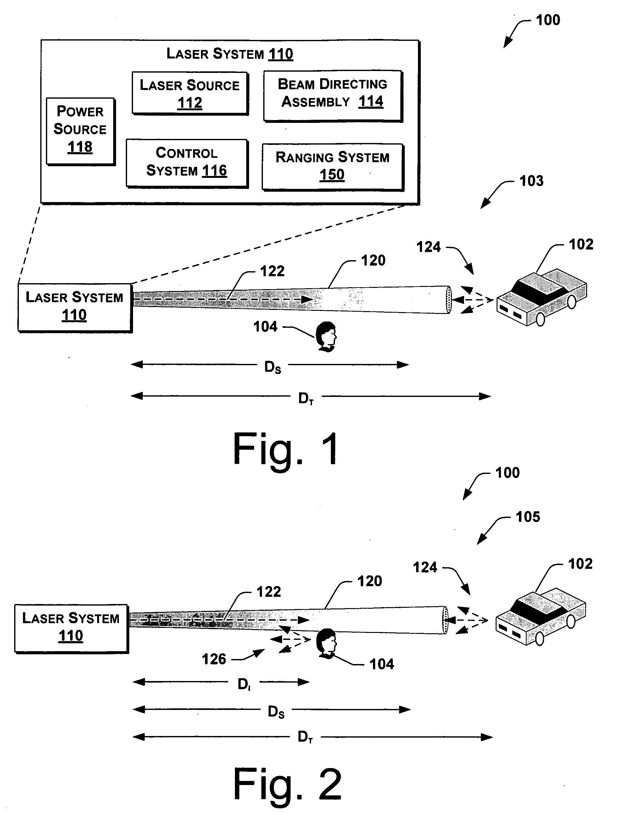
[0020]FIG. 1 is an exemplary environment 100 having a laser system 110 in accordance with an embodiment of the present disclosure. In a first operating condition 103, the laser system 110 directs a laser beam 120 along a beam axis 122 toward a target 102. The laser beam 120 may be a pulsed or non-pulsed laser beam 120. As depicted by the gradually-decreasing shading of the laser be...
PUM
 Abstract
Description
Claims
Application Information