Conductive polymer sheath on defibrillator shocking coils

a shock coil and polymer technology, applied in electrotherapy, therapy, etc., can solve the problems of time-consuming and labor-intensive explanting of shock coils, potential surgical risks, and increased fibrotic tissue growth between coils, so as to minimize or eliminate direct contact of shock coils, the effect of reducing the risk of surgical complications

Inactive Publication Date: 2010-07-13
CARDIAC PACEMAKERS INC
View PDF23 Cites 16 Cited by
  • Summary
  • Abstract
  • Description
  • Claims
  • Application Information

AI Technical Summary

Benefits of technology

[0007]In accordance with the present invention, there is provided an implantable cardiac lead having a distal end that includes a fixation tip and a tissue stimulating electrode, wherein the electrode is covered by a pliable, electrically conductive sheath. The fixation tip of the lead according to the present invention may include tines or a helix screw for providing fixation. It is known that the fibrosis at the site of the fixation tip of the lead is beneficial as it assists in retaining the lead in its implanted site.
[0008]Where the lead is a transvenous defibrillator lead for correcting ventricular tachycardia, the tissue stimulating electrode comprises a helically wound coil formed of uninsulated wire. After implantation of such a lead, there is extensive fibrotic tissue growth between the coil turns and around the shocking coils. Explanting such defibrillator leads is time consuming and carries potential surgical risk. In one embodiment a pliable sheath covers at least a portion of the shocking coils, thereby minimizing or eliminating direct contact of the shocking coil with the biological environment. The construction of the sheath is such that it can transfer electrical energy from the surface of the shocking coil. At least a portion of the outer surface of this sheath is adapted to stimulate cardiac tissue, by being inherently conductive, without relying on porosity and body fluid for charge transfer.

Problems solved by technology

After implantation of such a lead, there is extensive fibrotic tissue growth between the coil turns and around the shocking coils.
Explanting such defibrillator leads is time consuming and carries potential surgical risk.

Method used


Image

  • Conductive polymer sheath on defibrillator shocking coils
  • Conductive polymer sheath on defibrillator shocking coils
  • Conductive polymer sheath on defibrillator shocking coils

Examples


Embodiment Construction

[0013]In the following detailed description of the preferred embodiments, reference is made to the accompanying drawings which form a part hereof wherein like numerals designate like parts throughout, and in which is shown by way of illustration specific embodiments in which the invention may be practiced. It is to be understood that other embodiments may be utilized and structural or logical changes may be made without departing from the scope of the present invention. Therefore, the following detailed description is not to be taken in a limiting sense, and the scope of the present invention is defined by the appended claims and their equivalents.

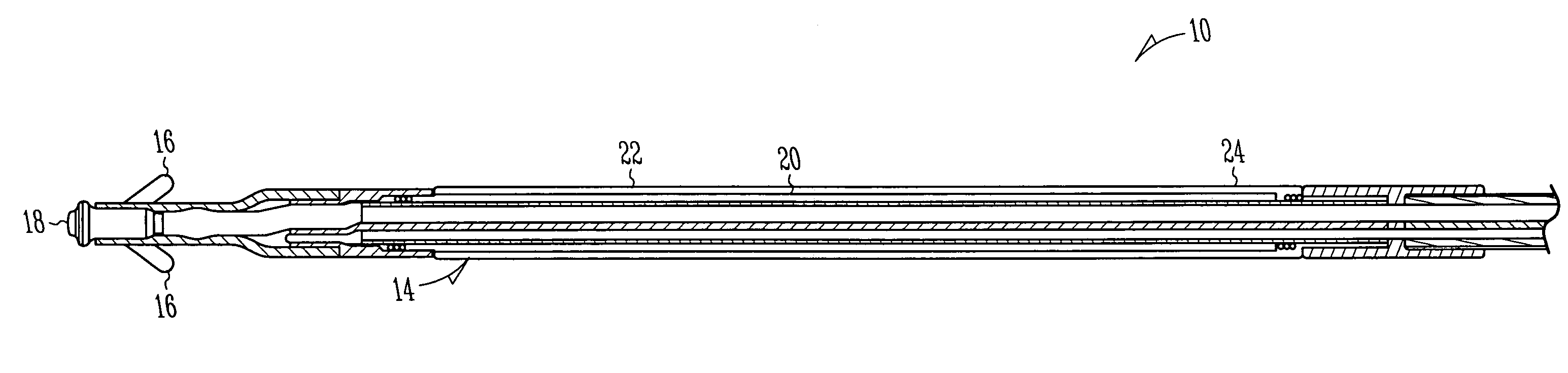
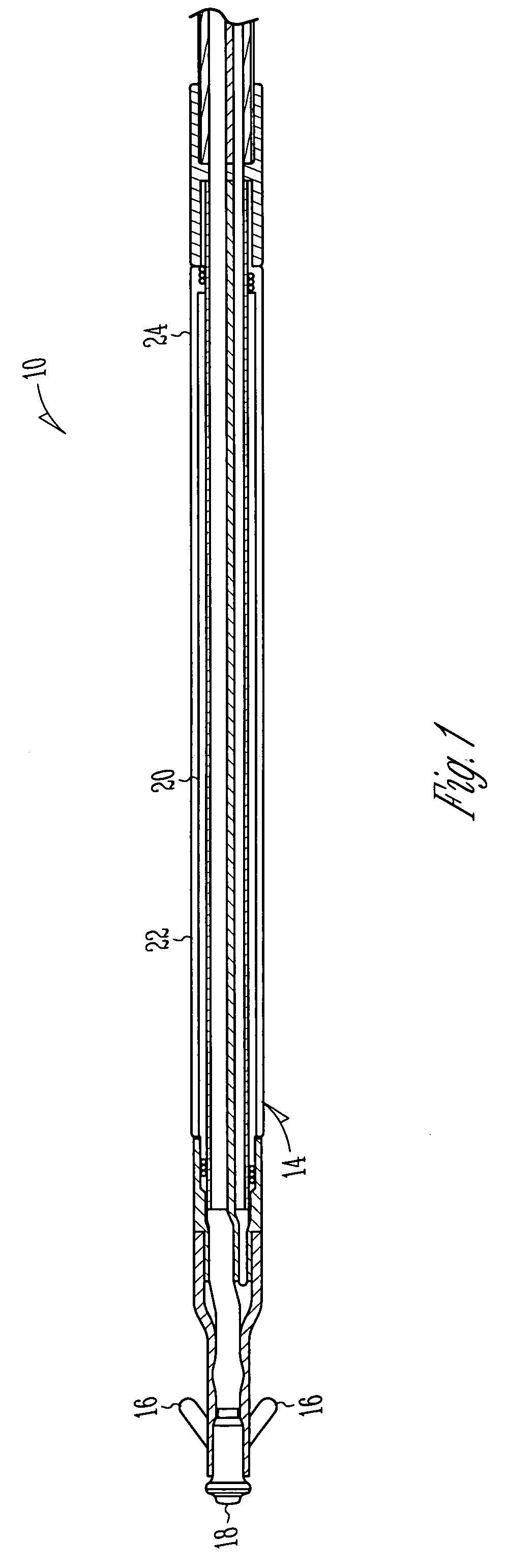
[0014]FIG. 1 shows a portion of an implantable endocardial lead, referred to generally at 10, in accordance with one embodiment of the present invention. The present invention contemplates any lead configuration known in the art, especially a suitable defibrillator lead configuration having a proximal end, a distal end and at least one ele...


PUM


Abstract

An implantable lead includes a distal portion carrying a tissue stimulating electrode, at least a portion of its outer surface being adapted to stimulate cardiac tissue, wherein the electrode is covered by a pliable, electrically conductive sheath. The sheath is made of an electrically conductive material that does not rely on porosity for electrical charge transfer. The sheath is constructed and arranged to minimize or eliminate tissue ingrowth while passing sufficient electrical energy to stimulate the tissue.

Description

CROSS-REFERENCE TO RELATED APPLICATION[0001]This application is a continuation of U.S. patent application Ser. No. 09 / 564,741, filed on May 4, 2000, now U.S. Pat. No. 7,013,182, the specification of which is incorporated herein by reference.FIELD OF INVENTION[0002]The present invention relates generally to implantable cardiac leads and particularly to transvenous defibrillator leads having a pliable electrically conductive sheath covering the shocking coils of such leads.BACKGROUND OF INVENTION[0003]An automatic implantable cardioverter defibrillator (AICD) or implantable cardioverter defibrillator (ICD) detects ventricular fibrillation and delivers a series of countershocks of sufficient energy to terminate the fibrillation. Such an ICD utilizes an electrode system either attached to the outer surface of the heart by means of a large surface area patch electrode, or inserted transvenously into or near the heart. Such an ICD system may be combined with a pacemaker function.[0004]Tra...

Claims


Application Information

Patent Timeline
Patent Type & Authority Patents(United States)
IPC IPC(8): A61N1/00
CPCA61N1/0563
Inventor KRISHNAN, MOHAN
Owner CARDIAC PACEMAKERS INC
Why Eureka
Try Eureka