Image generation device

a technology of image generation and image, applied in scene recognition, traffic control systems, instruments, etc., can solve the problems of difficult to identify substitute images and actual 3d obstacles, difficult for drivers to obtain distance, and present difficulty in visual recognition, so as to achieve better visibility

Inactive Publication Date: 2014-03-06
AISIN SEIKI KK
View PDF9 Cites 93 Cited by
  • Summary
  • Abstract
  • Description
  • Claims
  • Application Information

AI Technical Summary

Benefits of technology

[0012]This inventive configuration is based on a finding that the discriminating identification between an actual 3D object and a substitute image on a display screen is improved by adding to the substitute image a color corresponding to the actual 3D object, whereby the visual recognizability between the actual 3D object and the substitute image is enhanced.
[0013]With the above-described configuration provided by the present invention, a recognized 3D object included in the photographed image will be included in the bird's-eye view image in the form of a substitute image distinctly showing the feature of this 3D object, in particular, its characteristic color. Therefore, the driver can readily recognize the 3D object present in the vehicle periphery from this bird's-eye view image attached with this substitute image.
[0018]When a recognized 3D object has a plurality of colors, it is preferred that the coloring be effected with the plurality of colors as much as possible. Hence, according to one preferred embodiment of the present invention, the substitute image coloration section is configured to determine a plurality of colors that characterize the 3D object, based on the color information and to paint the substitute image with the plurality of different colors. As a method of painting a substitute image with a plurality of different colors, it is proposed to calculate an average color of the lower half of the height of 3D object and an average color of the upper half of the height of 3D object in the photographed image and to paint the lower half and the upper half of the height of the 3D object with these respective average colors. Further, considering that the painting area of the substitute image is small, it is effective to increase the chroma of the average color so as to realize coloration with conspicuous colors.
[0028]Further, preferably, the device further comprises a bird's-eye view photographed image generation section for generating a bird's-eye view photographed image of the vehicle periphery from a plurality of photographed images covering the periphery of the vehicle and having different photographing directions, with using projection transformation; and the image synthesis section applies the substitute image to the 3D object image area of the bird's-eye view photographed image. In this, with a peripheral bird's-eye view image obtained by a projection transformation processing using an upper viewpoint, if the 3D object is present in front of the camera, there occurs a distortion of the top portion of the 3D object being elongated. For this reason, with the addition of the substitute image as provided by the above-described configuration, it is possible to make correction for better visibility of the 3D object.

Problems solved by technology

However, with a bird's-eye view obtained through such projection transformation, there occurs signification distortion in the image for a faraway region as compared with a region nearby the in-vehicle camera, which distortion makes it difficult for the driver to obtain the sense of distance.
Especially, a three-dimensional (“3D” hereinafter) object (this can be not only a human, a vehicle, but also an on-road obstacle such as a road (traffic) cone for a construction work) placed on the road surface and extending upward therefrom will be shown as a deformed shape object elongated in the photographing direction, thus presenting difficulty in visual recognition.
However, in case a substitute image is displayed in place of the obstacle image imaging the actual 3D obstacle, there can sometimes happen a situation in which the driver finds it difficult to identify the substitute image and the actual 3D obstacle.
For instance, when the detected 3D obstacle is a human and an image of human represented in the form of an illustration (or an icon) or a photo is displayed, if the display screen is small, it is difficult to determine whether the human image on the display screen is identical to the actual human confirmed via a rearview mirror or the driver's eyes.
Also, in case the display screen is small, it can become difficult even to recognize that the image represents a human.
Moreover, if the substitute image shows a forward facing human although the actually recognized human is assuming a rearward facing directional posture, the identification becomes difficult.
Further, in case a detected 3D obstacle is an automobile, if the substitute image shows a sedan facing forward although the actually recognized automobile is a minivan facing rearward, the identification becomes difficult similarly.

Method used


Image

  • Image generation device
  • Image generation device
  • Image generation device

Examples


first embodiment

1. First Embodiment

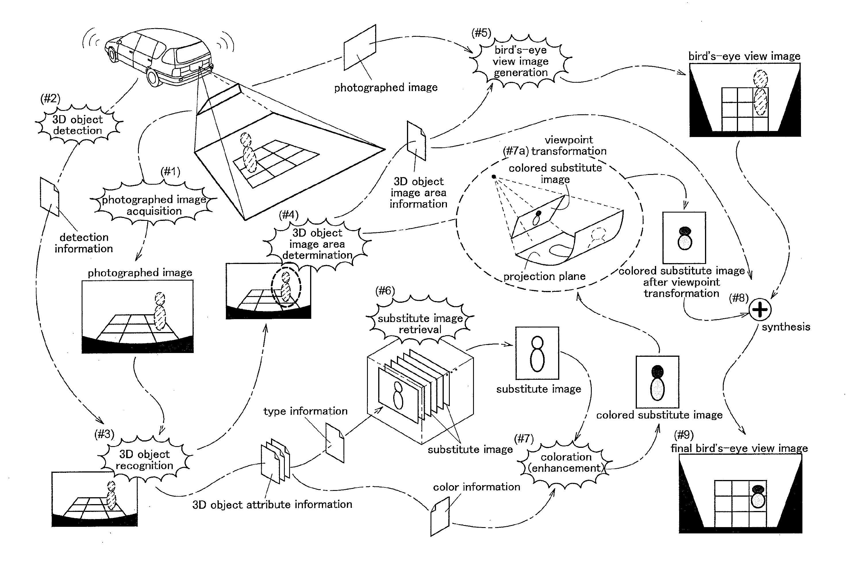
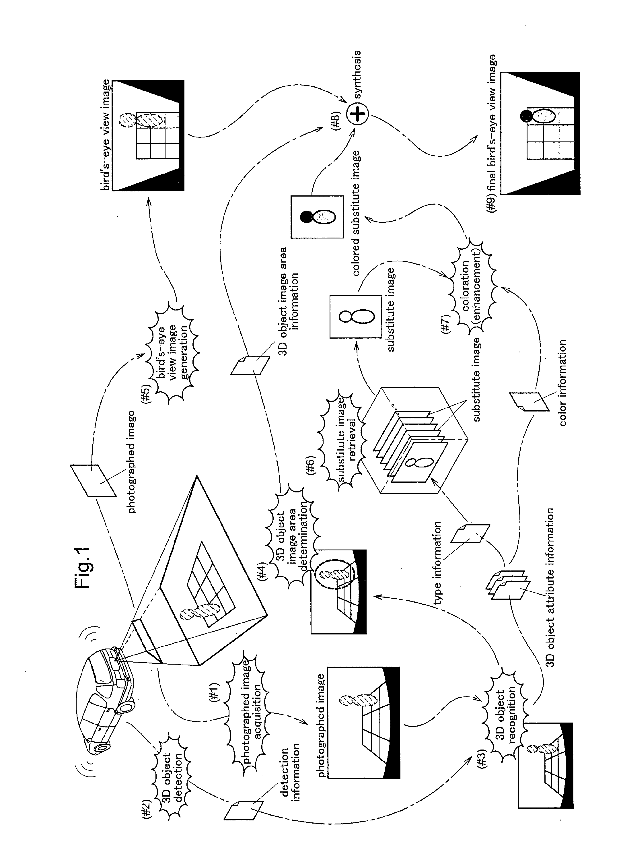
[0045]Firstly, if a recognized 3D (three-dimensional) object is included in a photographed image of an in-vehicle camera, a bird's-eye view image comprising a 3D object image substituted by a substitute image is produced. Now, the basic concept of a bird's-eye view image producing process relating to the first embodiment of the present invention will be explained with reference to the schematic diagram of FIG. 1. For the sake of simplicity of the explanation, there is illustrated production of a bird's-eye view image using only a photographed image of a rear camera as an in-vehicle camera. In general, however, a bird's-eye view image of vehicle periphery centering about the vehicle will be produced from photographed images from front and rear cameras and left and right side cameras.

[0046]For monitor displaying of a bird's-eye view image as a vehicle periphery monitoring screen, firstly, a photographed image of the peripheral area of the self vehicle along its trav...

second embodiment

2. Second Embodiment

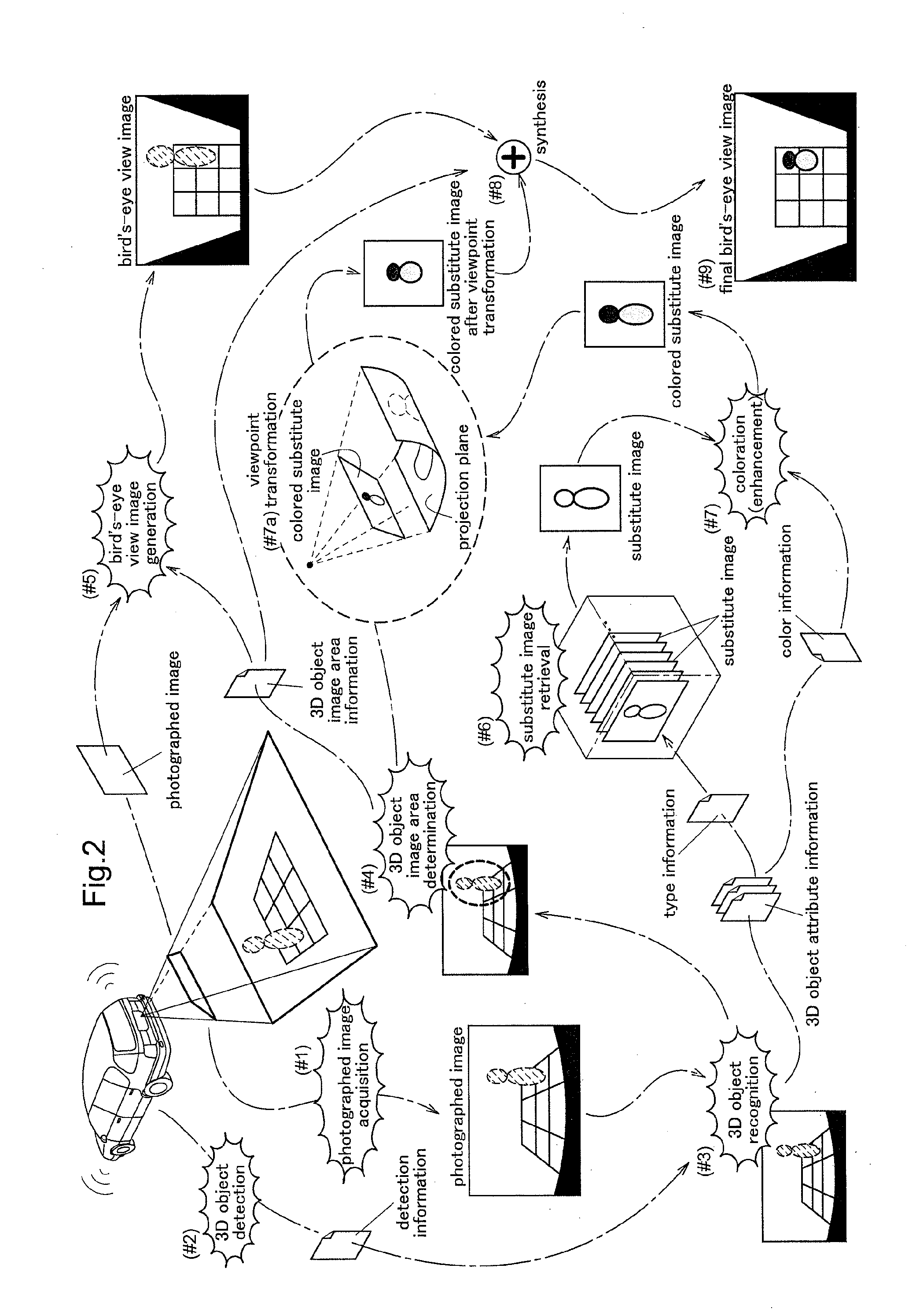
[0085]Next, a second embodiment will be explained. The basic concept of generation process of bird's-eye view image relating to the second embodiment will be explained with reference to the diagram in FIG. 8. Here, for the sake of simplicity of explanation, there will be shown generation of a bird's-eye view image with using only a photographed image of the rear camera as an in-vehicle camera. In general, however, there will be generated a vehicle periphery bird's-eye view centering about the self vehicle from photographed images of the front and rear cameras and the right and left side cameras.

[0086]For monitor displaying of a bird's-eye view image as a vehicle periphery monitoring image, firstly, a photographed image of the periphery area of the self vehicle along its traveling direction is obtained by the in-vehicle camera (#1). Here, the obtained photographed image is utilized also for detection of a 3D object as an obstacle present in the vehicle periphery. ...


PUM


Abstract

An image generation device that enhances visual recognizability between a recognized 3D (three-dimensional) object and a substitute image synthesized in an area of a 3D object image which is a photographed image of the 3D object includes an image synthesis section that recognizes a 3D object present in the peripheral area of a vehicle and outputs 3D object attribute information indicative of attributes of this 3D object, determines a 3D object image area as an image area of the 3D object in the photographed image based on position information included in the 3D object attribute information, outputs at least one of a substitute image of the 3D object applied with a color based on the color information and a substitute image of the 3D object under a specified directional posture of the 3D object specified based on type information and directional posture information and generates a bird's-eye view image with a substitution image in which the substitution image outputted from a substitution image output section is synthesized at the position of the 3D object image area.

Description

TECHNICAL FIELD[0001]The present invention relates to an image generation device configured to output, as a displaying image, a bird's-eye view image generated by projection transformation with an upper virtual viewpoint of a photographed image obtained by an in-vehicle camera for photographing a peripheral area of a vehicle.BACKGROUND ART[0002]With a conventional bird's-eye view generation device, a bird's-eye view from immediately above the self vehicle is generated by projecting a photographed image obtained by an in-vehicle camera onto a projection plane parallel with the road surface, that is, through projection transformation with a virtual viewpoint being located perpendicularly upwards. Therefore, by displaying this bird's-eye view on a monitor, the driver's grasping of the road surface situation of the vehicle surrounding is assisted. However, with a bird's-eye view obtained through such projection transformation, there occurs signification distortion in the image for a far...

Claims


Application Information

Patent Timeline
Patent Type & Authority Applications(United States)
IPC IPC(8): G06K9/00
CPCG06K9/00255G06K9/00805G08G1/166B60R2300/607G06T3/00H04N7/18G06T11/001G06T15/205G06V20/58G06V40/166
Inventor YAMAMOTO, KINJIWATANABE, KAZUYATAKEDA, SHOKOMIURA, KENJIKADOWAKI, JUN
Owner AISIN SEIKI KK
Why Eureka
Try Eureka