Robot

Active Publication Date: 2014-03-06
SEIKO EPSON CORP
View PDF22 Cites 22 Cited by
  • Summary
  • Abstract
  • Description
  • Claims
  • Application Information

AI Technical Summary

Benefits of technology

[0012]An advantage of some aspects of the invention is to provide a robot that can ea

Problems solved by technology

Thus, there is a problem in that vibration may be easily generated in the arm link portions due to the rotation of the arm link portions or disturbance applied to the arm link portions.
First, since the acceleration sensor is installed at the tip portion of the arm link portion closest to the tip side, the acceleration detected by the acceleration sensor is converted and corrected into those as the respective joint portions. At this time, since it is necessary to perform coordinate axis transformation referred to as the Jacobi's transformation, and matrix calculation having a number of products of sine and cosine as factors is required, the amount of calculation becomes huge. Since it is necessary to calculate the factors according to the rotation angles of the motors of the respective joint portions that change every moment, it is always necessary to execute huge calculation. Accordingly, there is a drawback in that response speed becomes slow.
Additionally, since accurate acceleration or speed cannot be fed back if calculation precision declines, vibration suppression capability may decline or control performance may be impaired.
Thus, it is difficult to correctly suppress vibration while stabilizing control.
That is, huge calculation is unnecess

Method used


Image

  • Robot
  • Robot
  • Robot

Examples


first embodiment

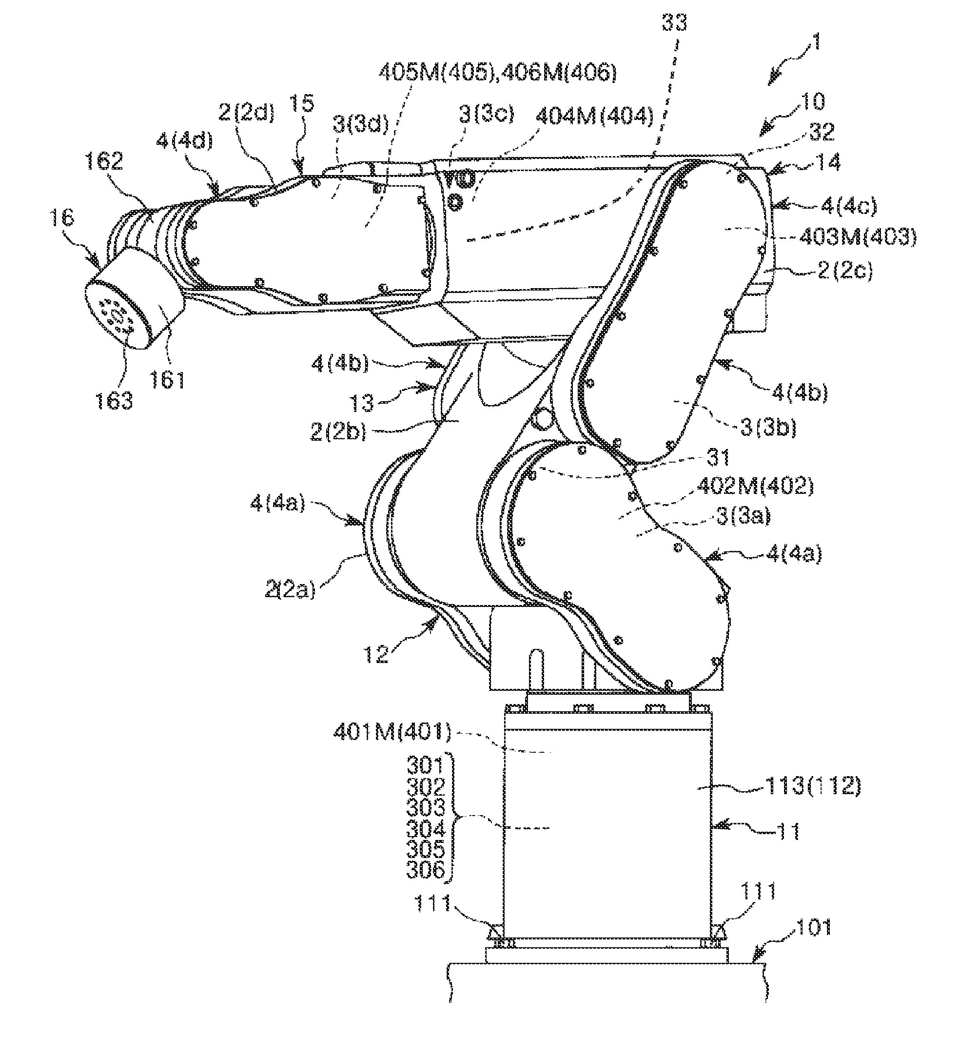
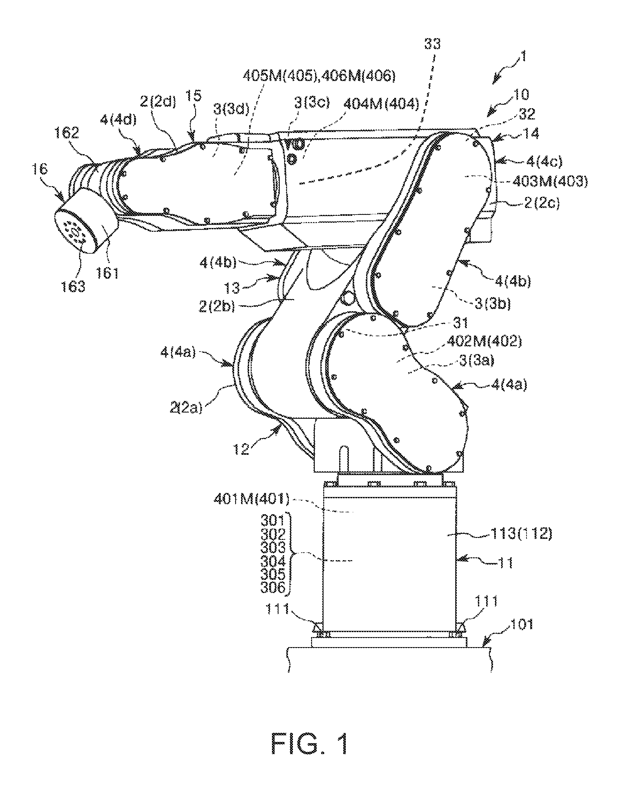
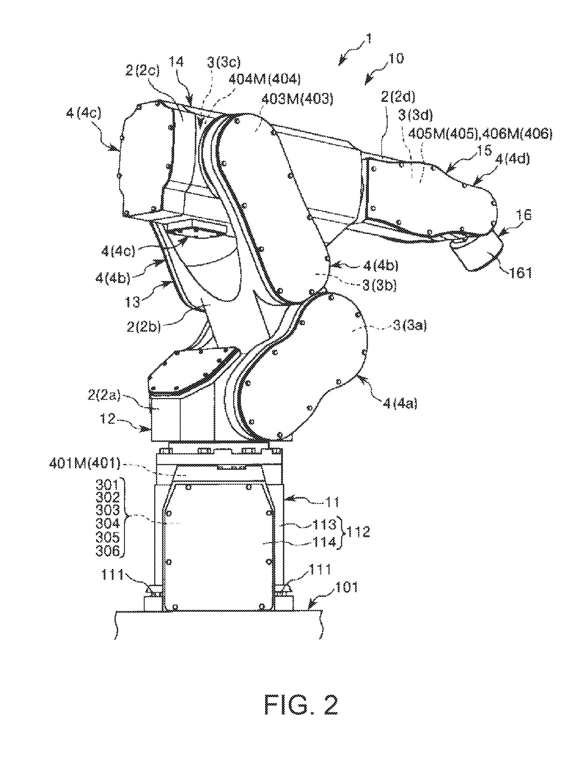
[0083]FIG. 1 is the perspective view when a first embodiment of a robot of the invention is viewed from the front side. FIG. 2 is a perspective view when the robot shown in FIG. 1 is viewed from the back side. FIGS. 3 and 4 are schematic views of the robot shown in FIG. 1, respectively. FIG. 5 is a block diagram of main portions of the robot shown in FIG. 1. FIGS. 6 to 10 are block diagrams of the main portions of the robot shown in FIG. 1, respectively. FIG. 11 is a flowchart showing the control operation of a control device of the robot shown in FIG. 1.

[0084]In addition, in the following, for the convenience of description, the upper side in FIGS. 1 to 4 and FIG. 6 is referred to as “upper” or “upside” and the lower side is referred to as “lower” or “downside”. Additionally, the base side in FIGS. 1 to 4 and FIG. 6 is referred to as a “base end”, and the opposite side is referred to as a “tip”. Additionally, the rotation axes O2 and O3 are shown in an exaggerated manner in FIG. 4,...

second embodiment

[0201]A second embodiment will be described below mainly regarding the differences from the aforementioned first embodiment, and the description of the same matters will be omitted.

[0202]In the robot 1 of the second embodiment, the second drive source controller 202 selects the inertia sensor to be used for the control of the operation of the second drive source 402 for suppressing the vibration in the second arm 13 by taking into consideration tip load mass at the tip portion of the robot 1, that is, at the tip portion of the wrist 16 in addition to the angle θ of the third arm 14. That is, the second drive source controller 202 selects any one of the second inertia sensor 32 and the third inertia sensor 33 by taking into consideration the tip load mass, and controls the operation of the second drive source 402 using a detection result of the selected inertia sensor.

[0203]This tip load mass is the total mass of the manipulator mounted on the tip portion of the wrist 16 that is an a...

third embodiment

[0215]FIG. 12 is a schematic view showing a third embodiment of the robot of the invention. FIG. 13 is a schematic view of the robot shown in FIG. 12. FIG. 14 is a block diagram of main portions of the robot shown in FIG. 12.

[0216]In addition, in the following, for the convenience of description, the upper side in FIG. 12 is referred to as “upper” and “upside” and the lower side is referred to as “lower” and “downside”. Additionally, the base side in FIGS. 12 and 13 is referred to as a “base end”, and the opposite side is referred to as a “tip”. Additionally, inertia sensors 31 and 32 are shown outside the arms 12 and 13 in FIGS. 12 and 13, respectively, in order to clarify the presence of the sensors.

[0217]The third embodiment will be described below mainly regarding differences from the aforementioned first embodiment, and the description of the same matters will be omitted.

[0218]A robot 1B of the third embodiment shown in FIGS. 12 and 13 is referred to as a scalar robot.

[0219]A r...


PUM


Abstract

A robot includes respective arms, respective drive sources, respective angle sensors, respective inertia sensors, a posture detection unit that detects the posture of a third arm, and a second drive source control unit that selects, on the basis of a detection result of the posture detection unit, any one of a second (A) correction component, which is derived from an angular velocity ωA3 of a second axis of a third arm obtained from a third inertia sensor, an angular velocity ωA2m of a second axis of a second arm obtained from a second angle sensor, and an angular velocity ωA3m obtained from a third angle sensor, and a second (B) correction component, which is derived from an angular velocity ωA2 obtained from a second inertia sensor and the angular velocity ωA2m, and feeds back the selected correction component to control the second drive source.

Description

BACKGROUND[0001]1. Technical Field[0002]The present invention relates to a robot.[0003]2. Related Art[0004]In the related art, a robot having a base and a plurality of arm link portions is known (for example, refer to JP-A-10-100085). Each arm link portion is rotatably coupled to the arm link portion on a base end side via a joint portion, and the arm link portion closest to the base side is rotatably coupled to the base via a joint portion.[0005]In such a robot, the rigidity of the joint portion that couples the base and the arm link portion or the rigidity of the joint portion that couples the arm link portion and the arm link portion is low compared to the base or the arm link portions due to spring elements of the joint portions. Thus, there is a problem in that vibration may be easily generated in the arm link portions due to the rotation of the arm link portions or disturbance applied to the arm link portions.[0006]Thus, in the robot described in JP-A-10-100085, an acceleratio...

Claims


Application Information

Patent Timeline
IPC IPC(8): B25J9/16
CPCY10S901/09B25J9/1656B25J9/1651
Inventor GOMI, AKIHIROMOTOYOSHI, MASAKI
Owner SEIKO EPSON CORP
Why Eureka
Try Eureka