Eureka AIR delivers breakthrough ideas for toughest innovation challenges, trusted by R&D personnel around the world.

Ground engaging shaft

Inactive Publication Date: 2014-03-20
SUTHERLAND PETER GLEN
View PDF3 Cites 10 Cited by
  • Summary
  • Abstract
  • Description
  • Claims
  • Application Information

AI Technical Summary

Benefits of technology

The present patent describes an apparatus for engaging a soil formation using a shaft with an auger section and a rotating first plate. A second plate can also be used that is independently rotatable and interlocks with the first plate using connectors with flanges. The technical effect of this invention is to provide a more effective way to engage soil formations and facilitate the drilling of holes for piles and other structures.

Problems solved by technology

One disadvantage of such methods is that the force required to drive such a member into the ground can be high requiring relatively large equipment or relatively small members to effectively penetrate the ground.
It will be appreciated that such limitations often limit the size of ground penetrating members that may be used in some locations where larger equipment is not able to access.
In particular, one situation in which such methods are used is where it is necessary to excavate a hole to access a buried structure or to expose a location where the work is to occur.
In many instances, it is not practical to excavate a large amount of soil due to the proximity of other structures or time constraints.
In particular, shoring using a plurality of timbers may be time consuming and inaccurate to install as each timber must be located individually.
These multiple steps increase the amount of time required to shore the excavation.
Disadvantageously, such shoring structures are also required to either be assembled within the excavation or pre-assembled and lowered into the excavation as a whole.
Where the assembled structure is lowered into the excavation as a whole, it may be possible for the shoring structure to partially collapse or otherwise impact and thereby disturb the excavation wall.
An additional difficulty with current excavation shoring methods, is that it is necessary to excavate the location before the shoring is put into place.
In many soil types, such as, for example, moist or soft soils, such unshored excavations may be prone to wall collapse before the shoring can be properly located.
The struts and other bracing members between shoring walls may also limit the access that workers and equipment has to the bottom of the shored excavation.

Method used


Image

  • Ground engaging shaft
  • Ground engaging shaft
  • Ground engaging shaft

Examples


Embodiment Construction

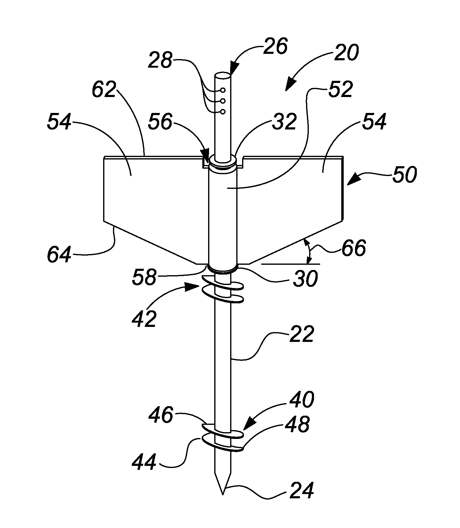
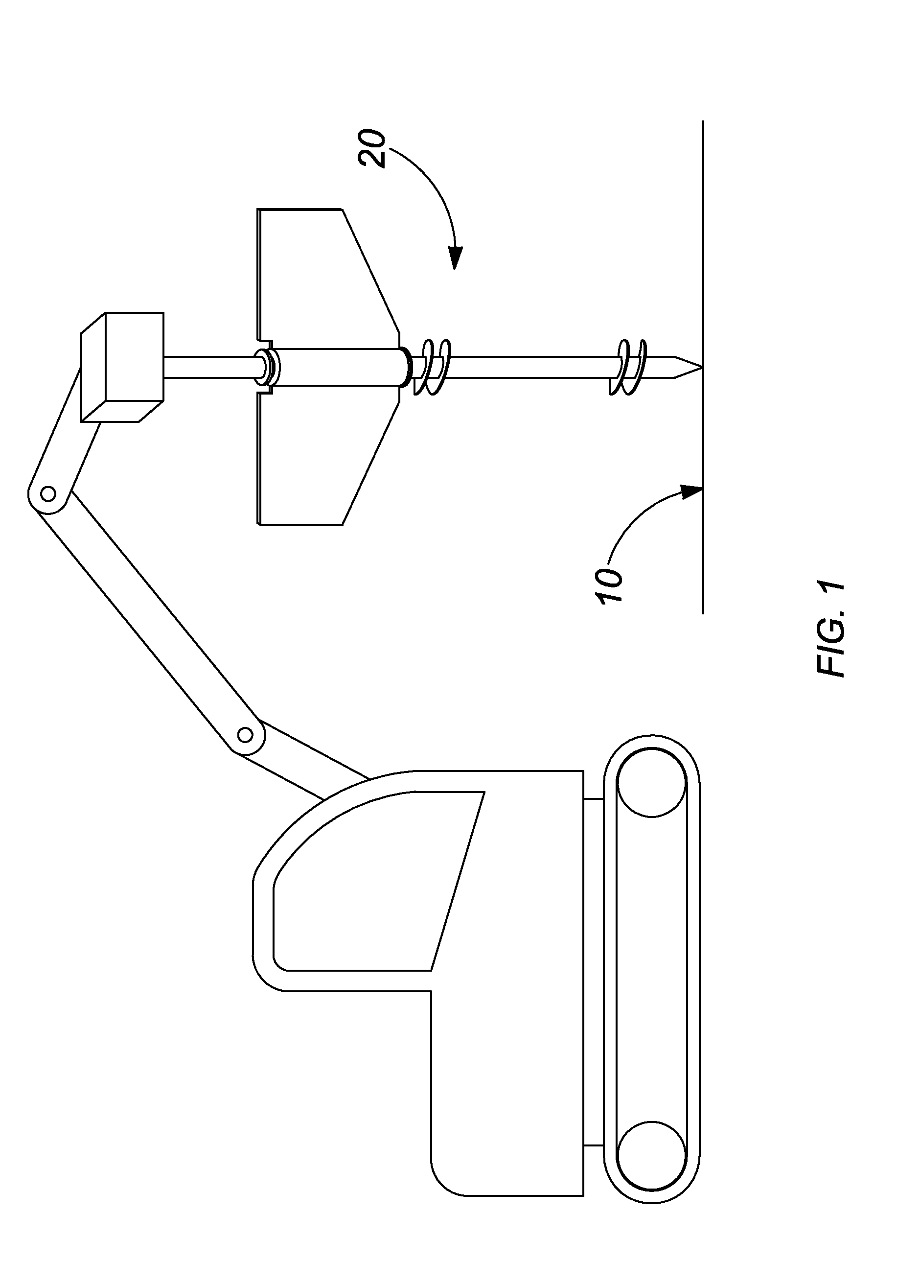
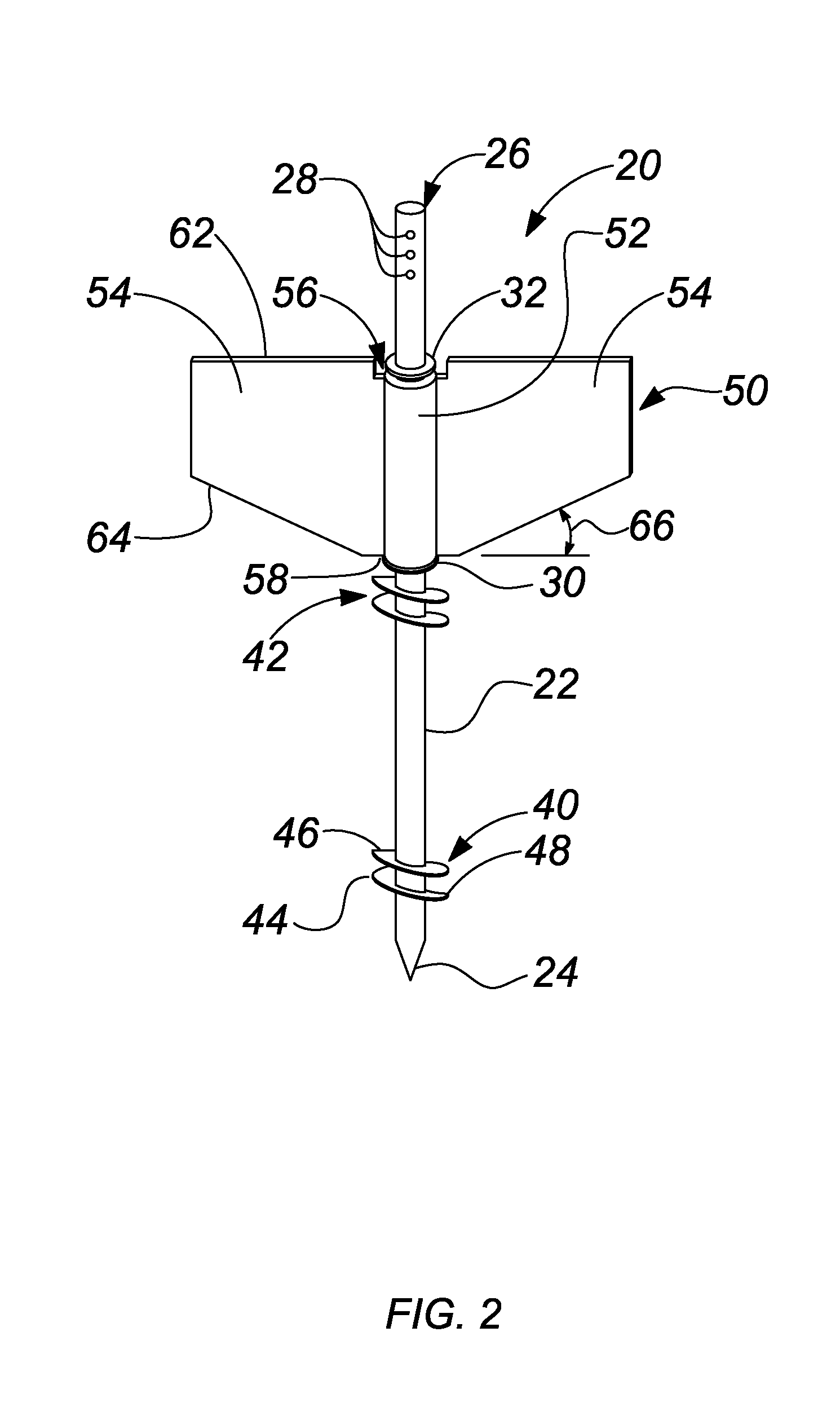
[0027]With reference to FIG. 1, an apparatus for engagement within a soil formation 10 according to a first embodiment of the present invention is generally illustrated at 20. The apparatus comprises an elongate shaft 22 having at least one auger 40 extending therearound and a plate 50 rotatably supported at a fixed location therealong. The apparatus 20 is operable to be rotated by a piece of equipment 8, such as, by way of non-limiting example, an excavator, skid steer loader or crane such that the augers 40 and 42 draw the apparatus into the soil formation 10 as will be more fully described below.

[0028]The shaft 22 extends between bottom and top ends, 24 and 26, respectively and may have a length of between 12 to 20 feet (3658 and 6096 mm) although it will be appreciated that other lengths may be useful as well. As illustrated, the bottom end 24 of the shaft may be sharpened to ease insertion into a soil formation and the top end may have a plurality of transverse bores 28 thereth...


PUM


Abstract

An apparatus and method for engaging a member within a soil formation. The apparatus comprises a shaft extending between top and bottom ends along a central axis and having at least one auger section therearound and a first plate, axially rotatably connected to the shaft. The apparatus may further comprise a second plate rotatably connected to the shaft above the first plate which may have connectors for engagement with a corresponding adjacent plate. The method comprises locating the shaft above a soil formation and rotating the shaft into the soil formation so as to draw the first plate into the soil formation.

Description

BACKGROUND OF THE DISCLOSURE[0001]1. Field of Disclosure[0002]The present disclosure relates to construction in general and in particular to a method and apparatus for engaging a member within a soil formation.[0003]2. Description of Related Art[0004]At many worksites, it is frequently necessary to engage a construction member within the ground for the purposes of securing the member therein or to reinforce or retain a portion of the ground behind the member. Such members may commonly be located within the soil formation by pile driving wherein the member is forcibly pressed into the ground by a backhoe, pile driver or the like. One example of when such methods may be utilized is for locating pilings within the ground.[0005]One disadvantage of such methods is that the force required to drive such a member into the ground can be high requiring relatively large equipment or relatively small members to effectively penetrate the ground. It will be appreciated that such limitations often...

Claims


Application Information

Patent Timeline
IPC IPC(8): E02D29/00E02D29/02E02D7/22E02D5/56
CPCE02D29/02E02D5/56E02D7/22E02D29/00
Inventor FOSTER, CLAYTON LEIGHSUTHERLAND, PETER GLEN
Owner SUTHERLAND PETER GLEN
Why Eureka
Eureka Blog
Learn More