Optical navigating apparatus and computer readable media can perform optical navigating method

Active Publication Date: 2014-04-10
PIXART IMAGING INC
View PDF4 Cites 0 Cited by
  • Summary
  • Abstract
  • Description
  • Claims
  • Application Information

AI Technical Summary

Benefits of technology

The present invention is an optical navigating apparatus and method that can save power by adjusting its operation according to the non-illuminating frequency, the non-catching frequency, and the computing frequency. Additionally, the invention can adjust the searching range to further reduce power consumption by decreasing data computing amount.

Problems solved by technology

However, in such method the power consumption is huge since the light source 101 continuously illuminates the surface 102, the image sensor continuously catches the image and the controller 103 continuously performs computing operations.
Particularly, the data computing amount and the power consumption significantly increase when the optical navigating apparatus moves in a high speed mode, since a higher frequency for illuminating, image catching and computing is needed corresponding to increased difficulty for the tracking operation.
The stored power correspondingly decreases, thus shortage issue of power endurance for the optical navigating apparatus such as the optical mouse is caused.

Method used


Image

  • Optical navigating apparatus and computer readable media can perform optical navigating method
  • Optical navigating apparatus and computer readable media can perform optical navigating method
  • Optical navigating apparatus and computer readable media can perform optical navigating method

Examples


Embodiment Construction

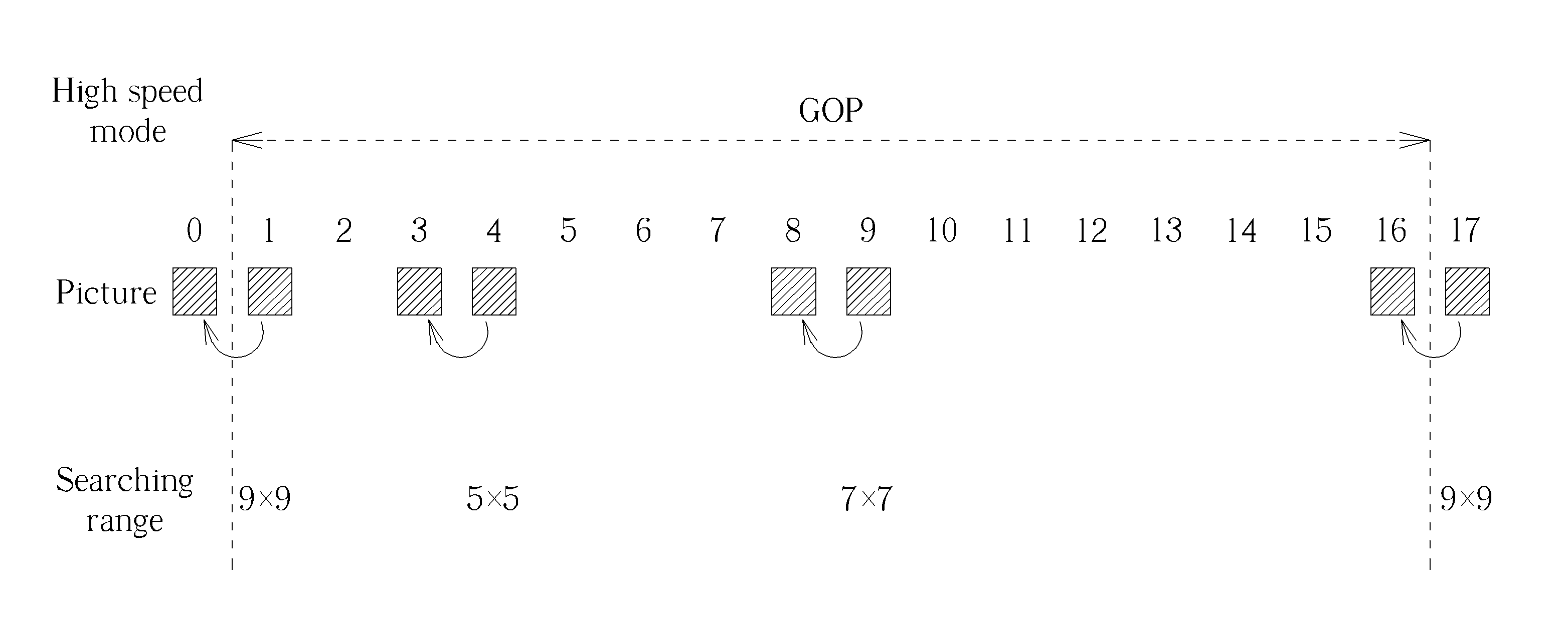
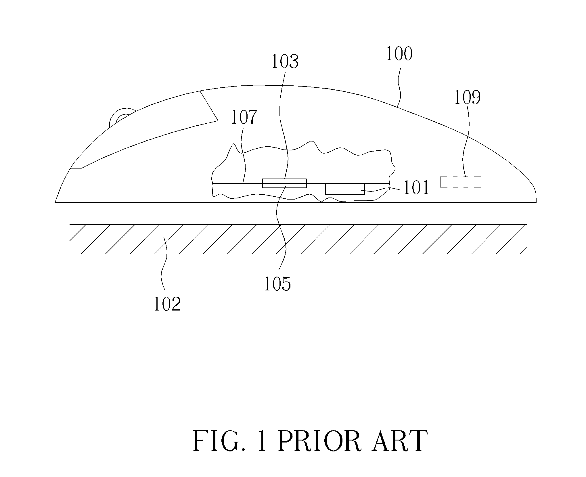
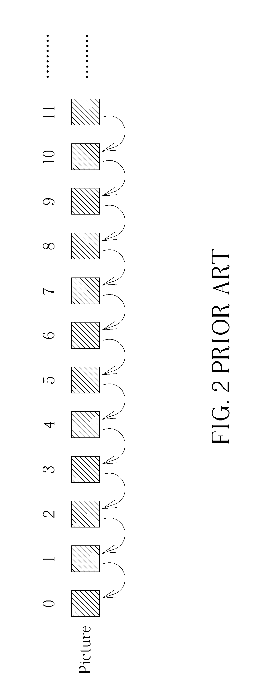
[0019]The tracking operation of the optical navigating apparatus of the present invention will be described as below. It should be noted that the optical mouse 100 shown in FIG. 1 is utilized as an example to explain the tracking operation of the present invention, but it does not mean that the present invention is limited to be applied to the optical mouse 100 shown in FIG. 1. Any optical navigating apparatus comprising a light source, an image sensor and a controller for controlling the light source and the image sensor should be included in the scope of the present invention. The embodiment of the present invention also utilizes the light source 101 in the optical mouse 100 to illuminate the surface 102 to generate an image, and utilizes the image sensor 105 to catch pictures in the image. The controller 103 in FIG. 2 continuously controls the light source 101 to illuminate the surface 102 and continuously computes caught pictures. However, the controller 103 applying the embodim...


PUM


Abstract

An optical navigating apparatus, which comprises: a light source, for illuminating a surface to generate an image; an image sensor, for catching pictures of the image; and a controller, for computing a first estimating speed of the optical navigating apparatus according to a first picture of the pictures and a second picture after the first picture. The controller controls at least one of parameters as following according to the first estimating speed: a non-illuminating frequency that the light source does not illuminate pictures after the second picture; a non-catching frequency that the image sensor does not catch pictures after the second picture; a computing frequency that the controller computes pictures after the second picture, which are caught by the image sensor; and a searching range for pictures after the second picture.

Description

BACKGROUND OF THE INVENTION[0001]1. Field of the Invention[0002]The present invention relates to an optical navigating apparatus, and a computer readable recoding media that can perform an optical navigating method, and particularly relates to an optical navigating apparatus, and a computer readable recoding media that can perform an optical navigating method, which can estimate a moving speed of the optical navigating apparatus and accordingly adjusts light emitting frequency.[0003]2. Description of the Prior Art[0004]A prior art optical navigating apparatus utilizes a light source to illuminate a surface to generate an image. Then, an image sensor is utilized to catch pictures in an image and the pictures are computed to compute a moving speed of the optical navigating apparatus to perform tracking.[0005]Please refer to FIG. 1, which illustrates a prior art optical mouse 100. An optical mouse is one kind of the optical navigating apparatuses. As shown in FIG. 1, the optical mouse ...

Claims


Application Information

Patent Timeline
IPC IPC(8): G06F3/03
CPCG06F3/0304G06F3/0317
Inventor CHEN, TZU-YUWU, CHIH-YEN
Owner PIXART IMAGING INC
Why Eureka
Try Eureka