Connector

Active Publication Date: 2014-04-10
JAPAN AVIATION ELECTRONICS IND LTD
View PDF3 Cites 12 Cited by
  • Summary
  • Abstract
  • Description
  • Claims
  • Application Information

AI Technical Summary

Benefits of technology

The technical effect of this patent is to provide a connector that makes it easy to check if it is properly installed on a circuit board and to avoid the difficulty of installing it.

Problems solved by technology

On the other hand, the contact 910 tends to be contaminated.
Accordingly, it is a cumbersome work to install the connector 950.

Method used


Image

  • Connector
  • Connector
  • Connector

Examples


first embodiment

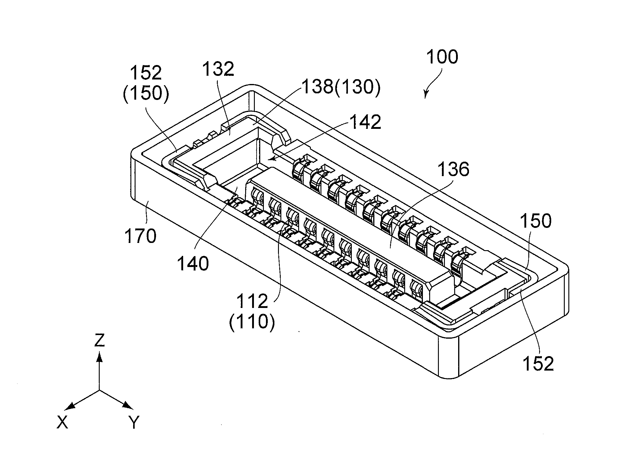
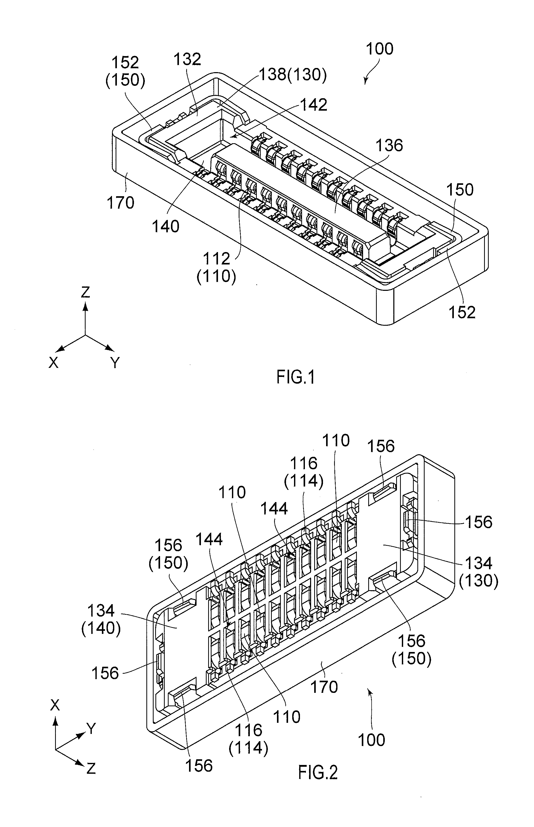
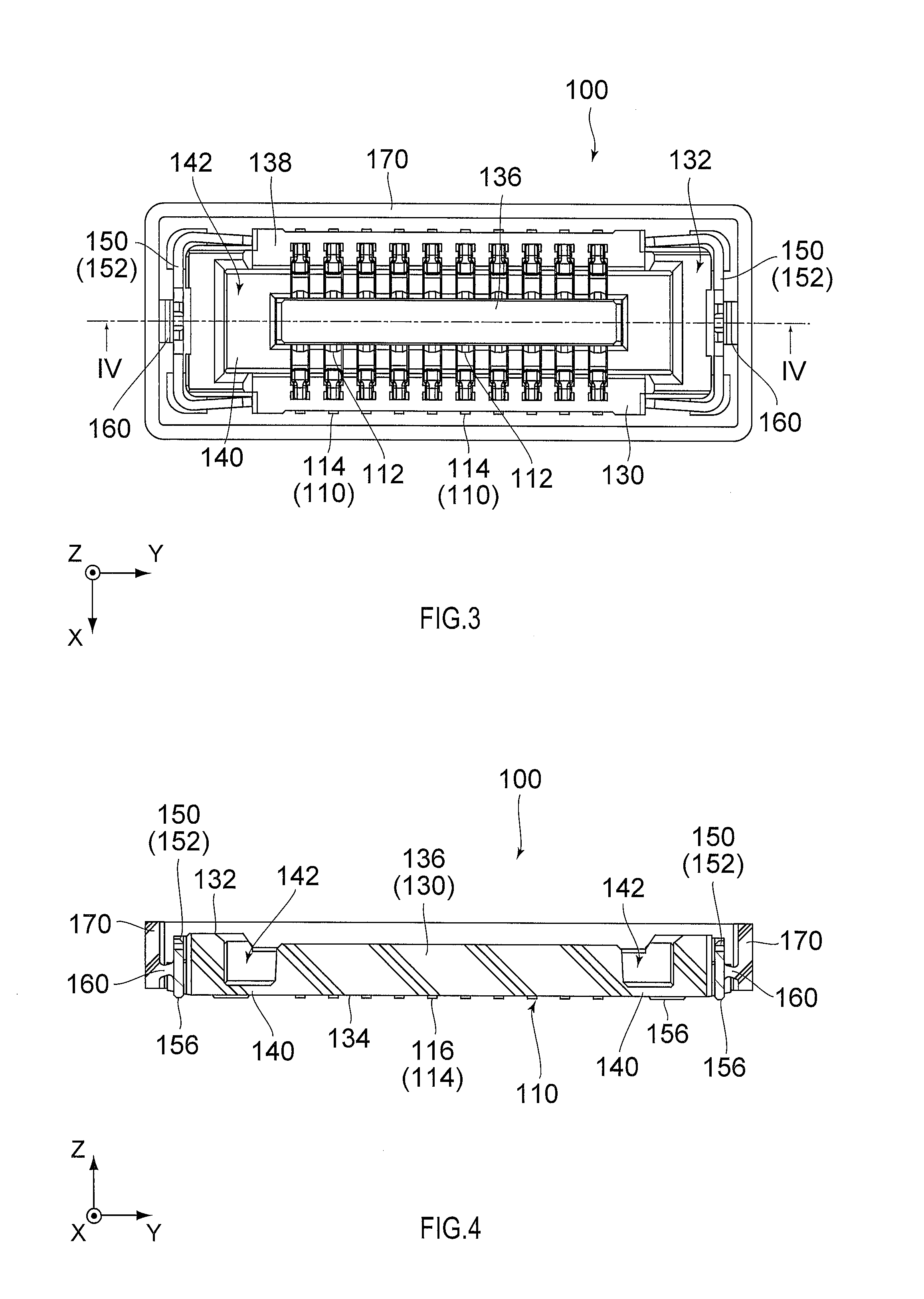
[0039]Referring to FIGS. 1, 10 and 11, a connector 100 according to a first embodiment of the present invention is a receptacle while a mating connector 200 is a plug. The connector 100 is mateable with the mating connector 200 along a mating direction (Z-direction). As shown in FIGS. 11 to 14, the connector 100 is used in a state where the connector 100 is mounted on a circuit board 500 while the mating connector 200 is used in a state where the mating connector 200 is mounted on a mating circuit board 600.

[0040]As shown in FIG. 10, the mating connector 200 comprises a plurality of contacts 210 each made of a conductive material and a housing 230 made of an insulating material. Each of the contacts 210 has a contact portion 212 and an SMT portion 214. The contact portions 212 are electrically connected with the connector 100 under a mated state where the connector 100 mounted on the circuit board 500 and the mating connector 200 mounted on the mating circuit board 600 are mated wit...

second embodiment

[0052]Referring to FIGS. 15 to 19, a connector 100A according to a second embodiment of the present invention is a modification of the connector 100 according to the aforementioned first embodiment. The connector 100A has a structure same as the connector 100 except differences in configurations of coupling portions 160A and enclosing portion 170A and a difference in a relation of the housing 130 and the reinforcement members 150 with the coupling portions 160A and the enclosing portion 170A. Moreover, the mating connector 200 is same as that of the first embodiment (see FIGS. 10 and 23). Accordingly, in the following description, a component of the connector 100A, which has the same structure as the component of the connector 100 according to the first embodiment, is referred to by using the same sign and simply described. In the following description, differences in the connector 100A are described in detail.

[0053]As shown in FIGS. 15 to 18, the connector 100A comprises a pluralit...


PUM


Abstract

A connector is mountable on a circuit board and mateable with a mating connector along a mating direction. The connector comprises a contact, a housing, an enclosing portion and a coupling portion. The housing holds the contact. The enclosing portion encloses an outer circumference of the housing in a plane perpendicular to the mating direction. The coupling portion directly or indirectly couples the enclosing portion with the housing so as to allow the enclosing portion to move along the mating direction relative to the housing.

Description

CROSS REFERENCE TO RELATED APPLICATIONS[0001]An applicant claims priority under 35 U.S.C. §119 of Japanese Patent Application No. JP2012-222703 filed Oct. 5, 2012.BACKGROUND OF THE INVENTION[0002]This invention relates to a connector configured to be mounted on a circuit board and configured to be mated with a mating connector.[0003]For example, this type of connector is disclosed in JP-A H10(1998)-106684 (Patent Document 1) or JP-A H10(1998)-172685 (Patent Document 2), contents of which are incorporated herein by reference.[0004]As shown in FIG. 27, the connector 900 of Patent Document 1 is mateable with a mating connector 940. The connector 900 comprises contacts 910, a housing 920 holding the contacts 910, and a shell 930 covering the housing 920. Each of the contacts 910 has a Surface Mount Technology (SMT) portion 912 configured to be fixed on a circuit board (not shown). The housing 920 and the shell 930 constitute a body portion of the connector 900. The connector 900 has a g...

Claims


Application Information

Patent Timeline
IPC IPC(8): H01R13/426
CPCH01R13/426H01R12/716H01R13/5219H01R12/73H01R13/20H01R12/71H01R13/5213H01R13/658
Inventor KOBUCHI, TOSHIRONISHIMURA, TAKAYUKIOBIKANE, HIROAKIARAI, KATSUMI
Owner JAPAN AVIATION ELECTRONICS IND LTD
Why Eureka
Try Eureka