Imaging control apparatus and method for generating a display image, and storage medium

Active Publication Date: 2015-12-17
CANON KK
View PDF5 Cites 2 Cited by
  • Summary
  • Abstract
  • Description
  • Claims
  • Application Information

AI Technical Summary

Benefits of technology

This patent allows users to easily change the range they are capturing while using image capturing technology. This makes it easier to get the desired shot without having to manually adjust the camera's settings.

Problems solved by technology

However, with the technique disclosed in Japanese Patent Laid-Open No. 2009-303179, the user cannot check the moving path during a preset tour and the capturing range while the camera is moved.
Accordingly, it has been difficult for the user to check whether the capturing ranges assumed by the user are covered with respect to the entire range that can be captured by the imaging apparatus when a preset tour is set.
This consequently creates a mismatch between the moving path and the capturing range of the imaging apparatus and those assumed by the user, causing a possibility that the user does not notice a tour setting error or omission.
In addition, in the case where the user checks the capturing range by actually moving the angle of view of the imaging apparatus, much time is required to perform the check.

Method used


Image

  • Imaging control apparatus and method for generating a display image, and   storage medium
  • Imaging control apparatus and method for generating a display image, and   storage medium
  • Imaging control apparatus and method for generating a display image, and   storage medium

Examples


first embodiment

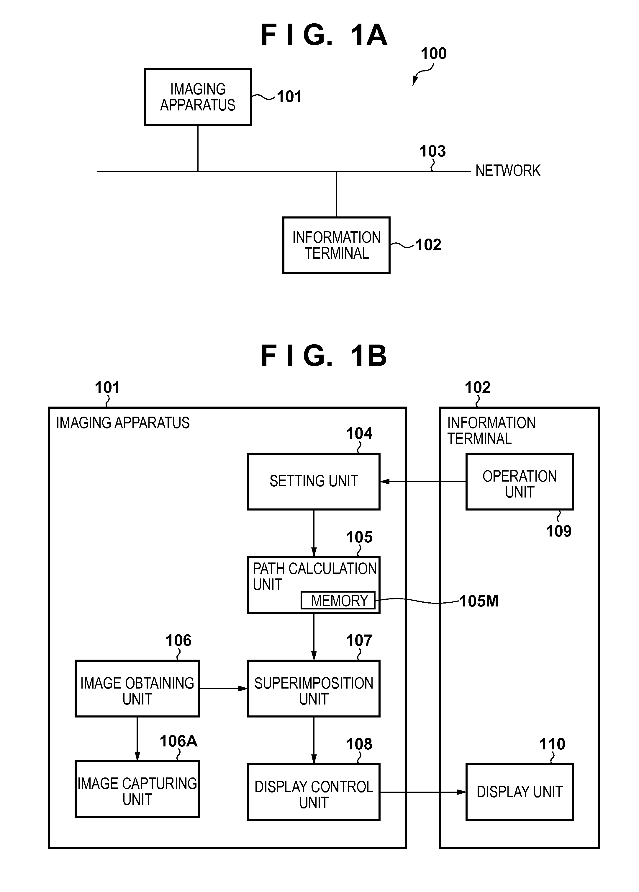
[0029]A first embodiment of the present invention will be described. FIG. 1A is a diagram showing a configuration of an imaging system according to the first embodiment. An imaging system 100 includes an imaging apparatus 101, an information terminal 102, and a network 103. The network 103 is a communication network such as the Internet, a WAN (Wide Area Network) or a LAN (Local Area Network), and includes a plurality of routers, switches, cables and the like.

[0030]The imaging apparatus 101 is a camera (network camera) having a variable angle of view, and is configured to distribute image data captured by the imaging apparatus via the network 103. The information terminal 102 is a computer configured to access the imaging apparatus 101 via the network 103 and perform operations such as making setting changes in the imaging apparatus 101, receiving image data captured by the imaging apparatus 101, and storing and displaying images based on the received image data.

[0031]There is no li...

second embodiment

[0084]In a second embodiment, an example of an imaging system capable of performing control so as to enable / disable the display of the moving path, the capturing range, the non-capturing range and the length of the capturing time will be described.

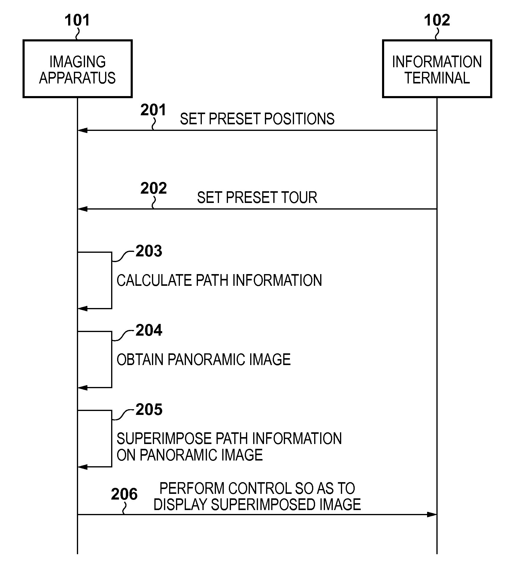
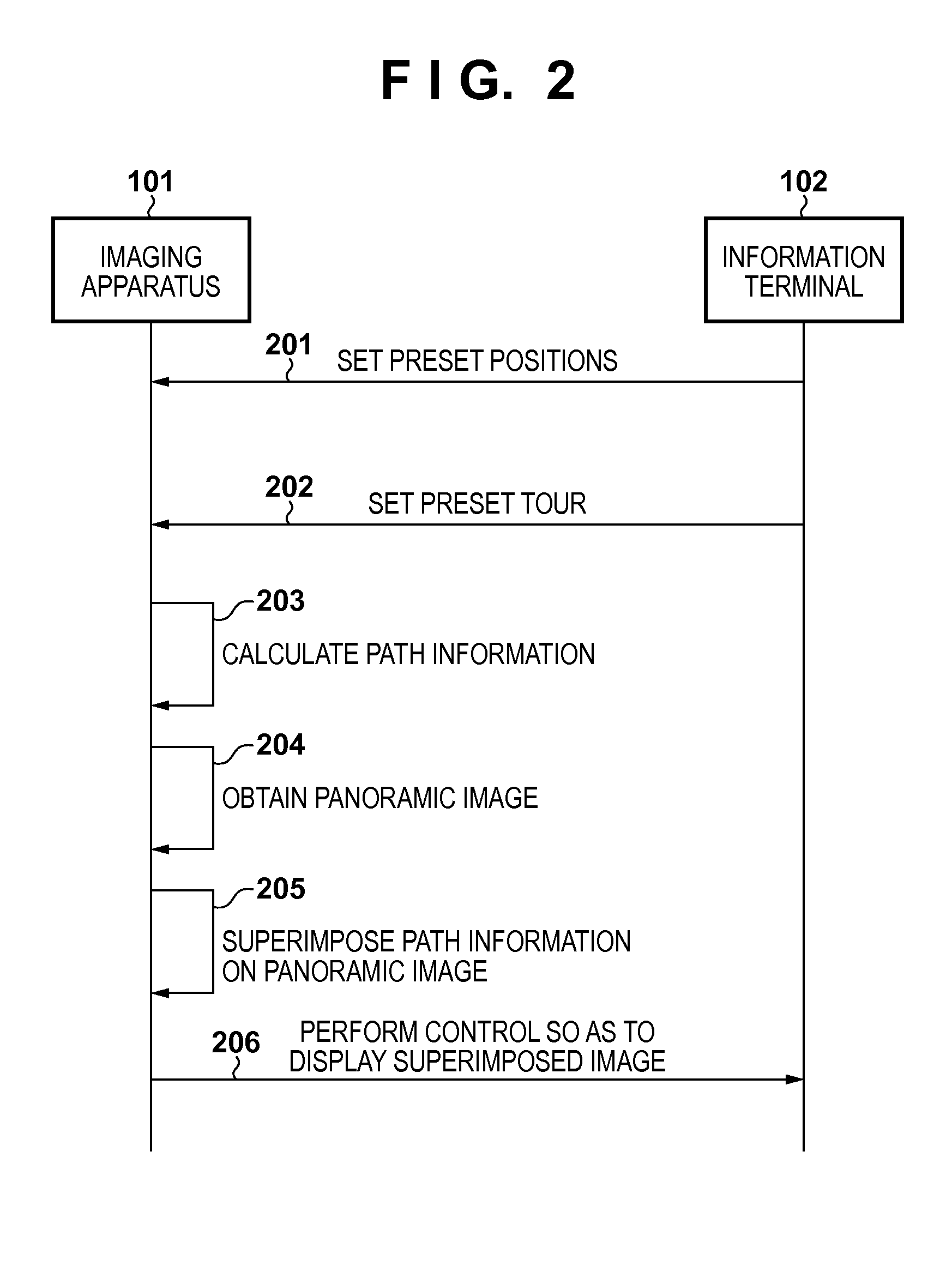
[0085]FIG. 11 is a sequence diagram in a system configuration according to the second embodiment. Processes 201 to 206 are the same as those described in the first embodiment. In the present embodiment, after the process 202, the operation unit 109 of the information terminal 102 transmits a command for making a path information display setting in the imaging apparatus 101 (1101). Then, the setting unit 104 of the imaging apparatus 101 makes a path information display setting based on the received command.

[0086]The processing performed by the path calculation unit 105 of the present embodiment will be described with reference to FIG. 3. In the present embodiment, in addition to the processing shown in FIG. 3, a determination is made betwee...

third embodiment

[0091]In a third embodiment, an example of an imaging system that further performs display of the moving path, the capturing range, the non-capturing range and the length of the capturing time based on settings that are set in the information terminal 102 and are not saved in the imaging apparatus 101 will be described.

[0092]FIG. 13 is a diagram showing a display screen according to the present embodiment. A panoramic image 1402 is a panoramic image on which path information calculated based on settings that are set in the information terminal 102 (before update) and are not saved in the imaging apparatus 101 is superimposed.

[0093]On the other hand, a panoramic image 1401 is a panoramic image on which path information calculated based on the settings saved in the imaging apparatus 101 (updated settings) is superimposed.

[0094]The display control unit 108 is capable of performing control so as to display the panoramic image 1401 and the panoramic image 1402 side by side as shown in FI...


PUM


Abstract

An imaging control apparatus that controls a capturing range in which an image is captured generates a display image showing a range to be captured by image capturing performed while the capturing range is changed from one of a plurality of predetermined capturing ranges to another one of the plurality of predetermined capturing ranges or a range not to be captured by the image capturing performed while the capturing range is changed from one of the plurality of predetermined capturing ranges to another one of the plurality of predetermined capturing ranges.

Description

BACKGROUND OF THE INVENTION[0001]1. Field of the Invention[0002]The present invention relates to an imaging control apparatus, a method for generating a display image, and a storage medium.[0003]2. Description of the Related Art[0004]In recent years, network cameras are used in a wide variety of applications such as monitoring and video conferencing. Some network cameras used in such applications are capable of providing pan, tilt and zoom (hereinafter, referred to as “PTZ” as appropriate) adjustments. Such network cameras may have a preset tour function of capturing images while moving the camera sequentially or randomly to preset positions which are pre-registered angles of views. According to conventional technology, in the preset tour, a path between preset positions is determined so as to be the shortest or quickest path.[0005]Meanwhile, there is a desire among users to want to know the details (the moving path, the capturing range while the camera is moved, and the like) of im...

Claims


Application Information

Patent Timeline
IPC IPC(8): H04N5/232H04N5/44H04N5/265
CPCH04N5/23238H04N5/44H04N5/265H04N5/23293H04N23/661H04N23/698H04N23/635
Inventor GOTO, TOMOHIRO
Owner CANON KK
Why Eureka
Try Eureka