Network Attach Method for Relay Node and Related Apparatus

Inactive Publication Date: 2014-04-17
HUAWEI TECH CO LTD
View PDF2 Cites 9 Cited by
  • Summary
  • Abstract
  • Description
  • Claims
  • Application Information

AI Technical Summary

Benefits of technology

[0012]In the preceding technical solutions, when the cell accessed by the RN is a base station cell that supports a relay function and allows being accessed by the RN, and the mobility management device serving the RN supports a relay function, the RN determines not to leave the accessed cell. Thereby, the RN does not need to execute the network reattach procedure in the second stage of the network attach procedure of the RN in the prior art, thereby optimizing the existing network attach procedure of the RN, reducing network attach time of the RN, and saving network resources.
[0013]In the preceding technical solutions, the mobility management device determines whether the cell currently accessed by the RN is a base statio

Problems solved by technology

In the prior art, the network attach procedure of the RN includes two stages, which greatly

Method used


Image

  • Network Attach Method for Relay Node and Related Apparatus
  • Network Attach Method for Relay Node and Related Apparatus
  • Network Attach Method for Relay Node and Related Apparatus

Examples


Embodiment Construction

[0024]The subsequent embodiments of the present invention provide a network attach method for an RN, a relay node, a mobility management device, and a network system. The technical solutions provided by the subsequent embodiments of the present invention may be applicable to a long term evolution (LTE) network and a future evolution of the LTE network, for example, an LTE Advanced network, and may be also applicable to a universal mobile telecommunications system (UMTS) network, but are not limited to the mentioned networks. The methods provided by the embodiments of the present invention may optimize the existing network attach procedure of an RN, reduce the network attach time of the RN, and save network resources.

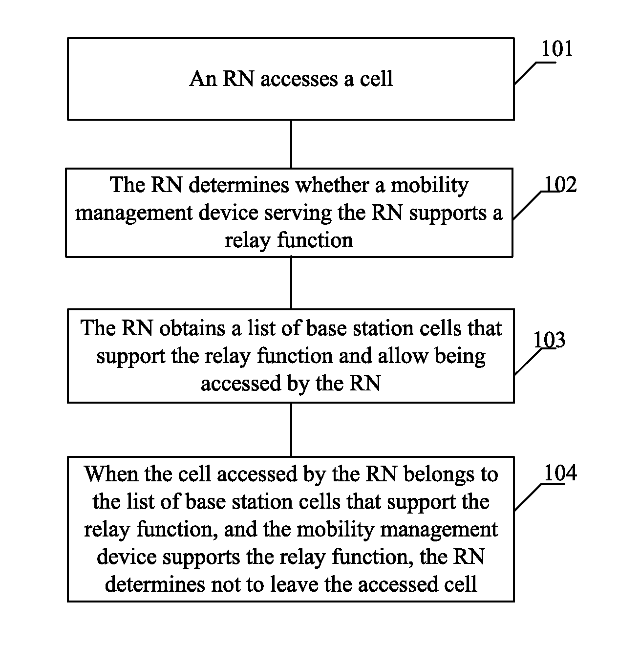
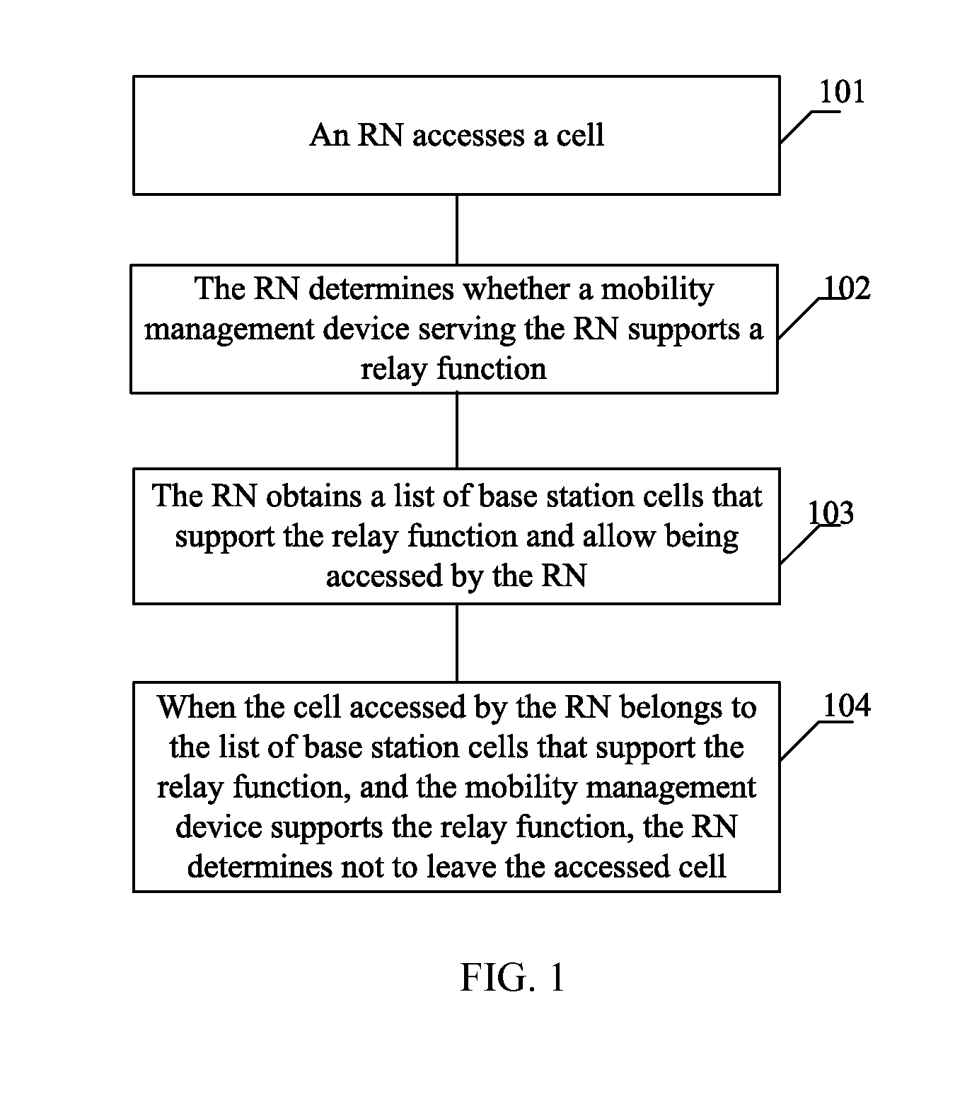
[0025]FIG. 1 illustrates a network attach method for an RN according to an embodiment of the present invention, where the method mainly includes the following steps.

[0026]Step 101: An RN accesses a cell.

[0027]The RN may access a cell in the following way. The RN randomly...


PUM


Abstract

A method is disclosed for a relay node (RN) attaching a network. The RN accesses a first cell. The RN obtains a list of cells that support a relay function and allow being accessed by the RN. When the first cell accessed by the RN is one of the cells in the list and a relay function of a mobility management device serving the RN is supported, not leaving, by the RN, the first cell.

Description

[0001]This application is a continuation of International Application No. PCT / CN2012 / 076956, filed on Jun. 15, 2012, which claims priority to Chinese Patent Application No. 201110162663.X, filed on Jun. 16, 2011, both of which are hereby incorporated by reference in their entireties.TECHNICAL FIELD[0002]The present invention relates to the field of communications technologies and, in particular embodiments, to a network attach method for a relay node (RN), a related apparatus, and a network system.BACKGROUND[0003]In the prior art, a network attach procedure for an RN includes two stages:[0004]The first stage includes the following process. The RN randomly selects a cell for access and sets up a connection with a base station to which the cell belongs. The base station selects a mobility management entity (MME) serving the RN. The MME exchanges information with a domain name system (DNS) server and selects a serving gateway (S-GW) or a public data network gateway (P-GW) serving the R...

Claims


Application Information

Patent Timeline
IPC IPC(8): H04W60/00H04B7/14H04W36/00H04W8/02H04W60/06
CPCH04W60/00H04W8/02H04B7/14H04W36/0083H04W60/06H04W24/02H04W84/047H04W36/00835H04W88/14
Inventor LIU, JINGPENG, YAN
Owner HUAWEI TECH CO LTD
Why Eureka
Try Eureka