Image forming apparatus

a technology of image forming apparatus and fixing device, which is applied in the direction of electrographic process apparatus, typewriters, instruments, etc., can solve the problems of inability to normalize image formation processing, the temperature of the sheet immediately after the image erased by heating with the fixing device is extremely high,

Active Publication Date: 2014-04-24
KK TOSHIBA +1
View PDF0 Cites 2 Cited by
  • Summary
  • Abstract
  • Description
  • Claims
  • Application Information

AI Technical Summary

Benefits of technology

This configuration allows for successful application of image formation processing using erasable ink on sheets that have been erased by the fixing device, ensuring the ink is not erased by heat, thus enabling normal image formation.

Problems solved by technology

However, the temperature of the sheet immediately after the image erased by heating with the fixing device is extremely high.
Even if it is attempted to apply the image formation processing by the erasable ink to the sheet immediately after the erasing having such high temperature, in some cases, the erasable ink is erased by the heat of the sheet immediately after the erasing and the image formation processing cannot be normally performed.

Method used


Image

  • Image forming apparatus
  • Image forming apparatus
  • Image forming apparatus

Examples


first embodiment

[0023]First, a first embodiment of the present invention is explained.

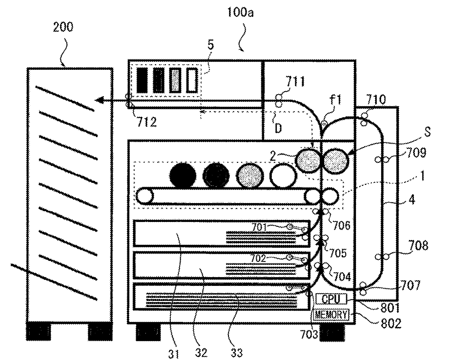
[0024]FIG. 1 is a longitudinal sectional view of the schematic configuration of an image forming system according to the first embodiment.

[0025]As shown in FIG. 1, the image forming system according to the first embodiment includes an image forming apparatus (a MFP: Multi Function Peripheral) 100a and a finisher 200.

[0026]The finisher 200 has a function of applying predetermined post-processing to a sheet discharged from an image forming apparatus 100a such as a sheet on which an image is formed by the image forming apparatus 100. Examples of the “predetermined post-processing” include stapling, punching, folding, sorting, and bookbinding.

[0027]The image forming apparatus (the MFR: Multi Function Peripheral) 100a includes a first image forming unit 1, a fixing device 2, cassettes 31 to 33, a reversal conveying path 4, a second image forming unit 5, sheet feeding rollers 701 to 703, conveying rollers 704 to 711, a ...

second embodiment

[0062]A second embodiment of the present invention is explained below.

[0063]The second embodiment is a modification of the first embodiment. Components same as those explained in the first embodiment are denoted by the same reference numerals and signs and explanation of the components is omitted.

[0064]FIG. 3 is a flowchart for explaining a flow of processing in an image forming apparatus according to the second embodiment. ACT 101, ACT 102, and ACT 104 shown in FIG. 3 are the same as ACT 101, ACT 102, and ACT 104 shown in FIG. 2. Therefore, only ACT 103′ is explained below.

[0065]The CPU 801 controls to drive the conveying rollers included in the sheet conveying unit to temporarily stop the sheet subjected to the erasing processing by the fixing device 2 in a period until the sheet reaches the second image forming unit 5 and, after securing sufficient cooling time, resumes the conveyance of the sheet and feeds the sheet to the second image forming unit 5 (ACT 103′).

[0066]FIG. 4 is a...

third embodiment

[0068]A third embodiment of the present invention is explained below.

[0069]The third embodiment is a modification of the embodiments explained above. Components having functions same as those of the components explained in the embodiments are denoted by the same reference numerals and signs and explanation of the components is omitted.

[0070]FIG. 5 is a longitudinal sectional view for explaining an image forming apparatus 100b according to the third embodiment.

[0071]The image forming apparatus 100b according to the third embodiment includes a cassette 35 (a second sheet feeding unit) as a sheet feeding unit exclusively for the second image forming unit 5. In the cassette 35, not only sheets not subjected to the image formation processing but also sheets subjected to the erasing processing while not being subjected to the image formation processing can be stacked.

[0072]The cassette 35 includes, between the fixing device 2 and the second image forming unit 5 in the sheet conveying dire...


PUM


Abstract

An image forming apparatus includes: a first image forming unit configured to form an image on a sheet using a first colorant to be heat-fixed on the sheet; a second image forming unit configured to form an image on the sheet using a second colorant that is erasable by heating; and a fixing device arranged further on a downstream side in a sheet conveying direction than the first image forming unit and further on an upstream side in the sheet conveying direction than the second image forming unit and capable of executing fixing processing for heat-fixing the image, which is formed on the sheet by the first image forming unit, on the sheet and executing erasing processing for heating the sheet, on which the image is formed with the second colorant, to erasing temperature to thereby erase the second colorant on the sheet.

Description

CROSS-REFERENCE TO RELATED APPLICATIONS[0001]This application claims benefit of U.S. patent application Ser. No. 13 / 910,845, filed Jun. 5, 2013, which claims benefit of U.S. patent application Ser. No. 12 / 699,286, filed Feb. 3, 2010, now U.S. Pat. No. 8,478,151, which claims the benefit of U.S. Provisional Application No. 61 / 150,262, filed on Feb. 5, 2009, and U.S. Provisional Application No. 61 / 150,263, filed on Feb. 5, 2009, each of which are herein incorporated by reference.TECHNICAL FIELD[0002]This specification relates to a technique for, in an image forming apparatus having both of an image forming function of heat-fixing a colorant on a sheet using a fixing device and an image forming function of forming an image on the sheet using a colorant erasable by heating, making it possible to apply normal image formation processing using the erasable colorant to a sheet on which the image is erased by the fixing device.BACKGROUND OF THE INVENTION[0003]In the past, there is known an i...

Claims


Application Information

Patent Timeline
Patent Type & AuthorityApplications(United States)
IPC IPC(8): G03G13/20
CPCG03G13/20B41J3/546B41J29/36G03G15/6558G03G15/6573G03G2215/00021G03G2215/0043G03G2215/00531G03G2215/0482G03G15/235G03G15/0194G03G13/22G03G15/0178
InventorIGUCHI, KENTAGUCHI, HIROYUKIYOSHIDATAKAGI, OSAMUKABAI, TAKAHITOKANEKO, YOSHIAKI
OwnerKK TOSHIBA