Control Circuit Device

a technology of control circuit and wearable device, which is applied in the direction of lighting and heating apparatus, light source combinations, and built-in power, etc., can solve the problems of power drain on the battery, no power left, and too sensitive vibration detection device embedded in the wearable devi

Active Publication Date: 2014-05-01
TSENG SHEN KO
View PDF5 Cites 1 Cited by
  • Summary
  • Abstract
  • Description
  • Claims
  • Application Information

AI Technical Summary

Benefits of technology

[0017]FIG. 3 is a schematic diagram illustrating the cross-sectional view of the control circuit device in another predetermined embodiment.

Problems solved by technology

However, the vibration detector embedded in the wearable device too sensitive in detecting vibration and will usually emit light when there was only a slight vibration.
This causes power drain on the battery due to LEDs emitting light when not necessary, which in turn may cause the LED to have no power left when it is needed.

Method used


Image

  • Control Circuit Device
  • Control Circuit Device
  • Control Circuit Device

Examples


Embodiment Construction

[0018]A detailed description of the described embodiments of the disclosed apparatus and method are presented by way of exemplification and not limitation with reference to the Figures. Although certain embodiments are shown and described in detail, it should be understood that various changes and modifications may be made while still maintaining the ideas and teachings of the appended claims. The scope of the present invention is in no way limited to the number of constituting components, the materials thereof, the shapes thereof, the relative arrangement thereof, etc., and are disclosed simply as an example of possible embodiments of the present invention.

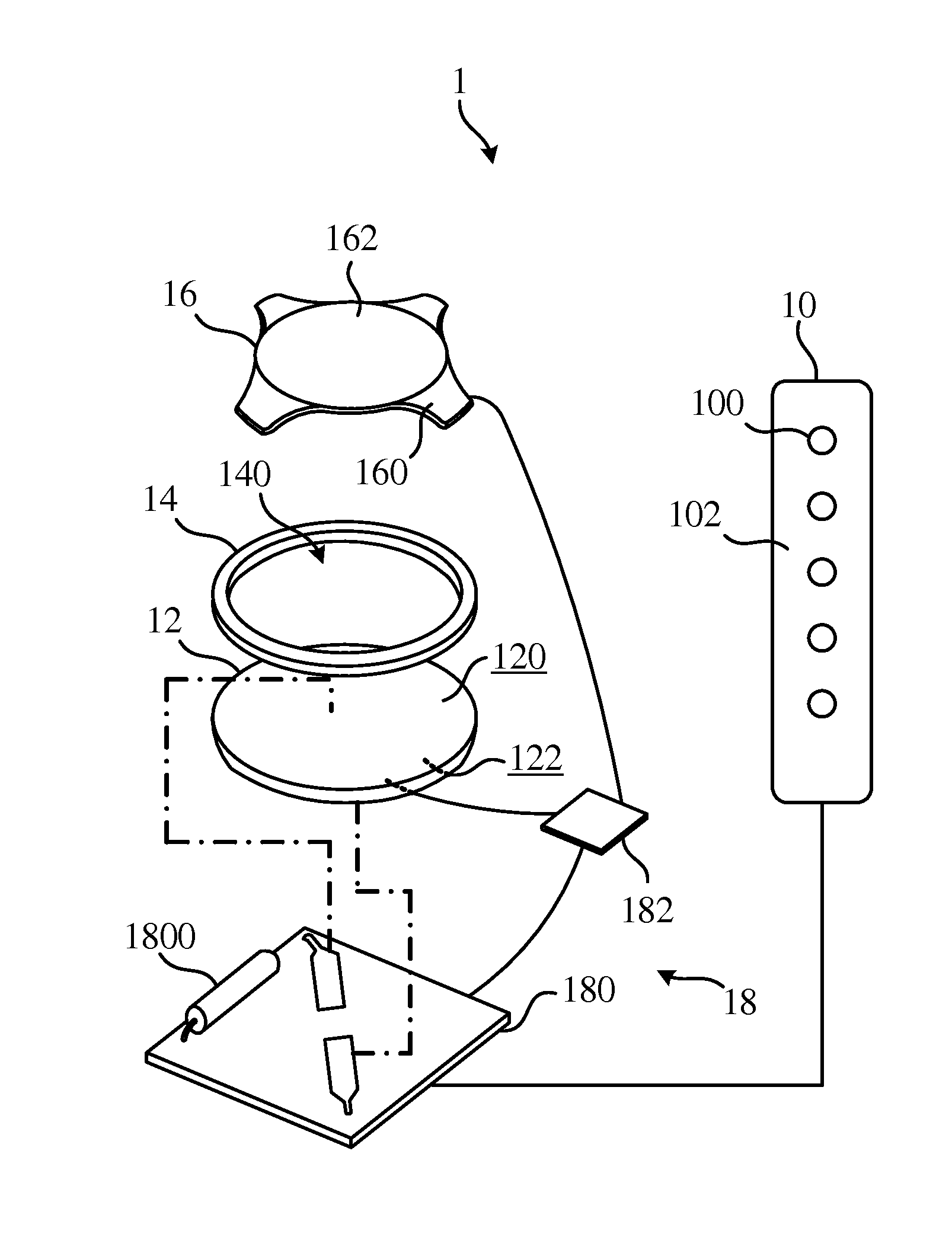
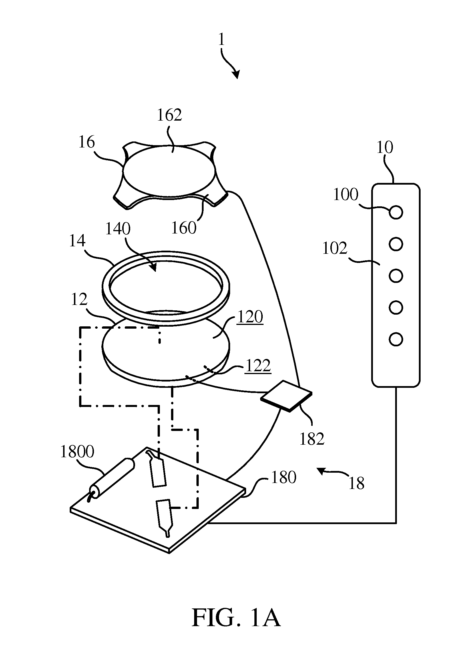
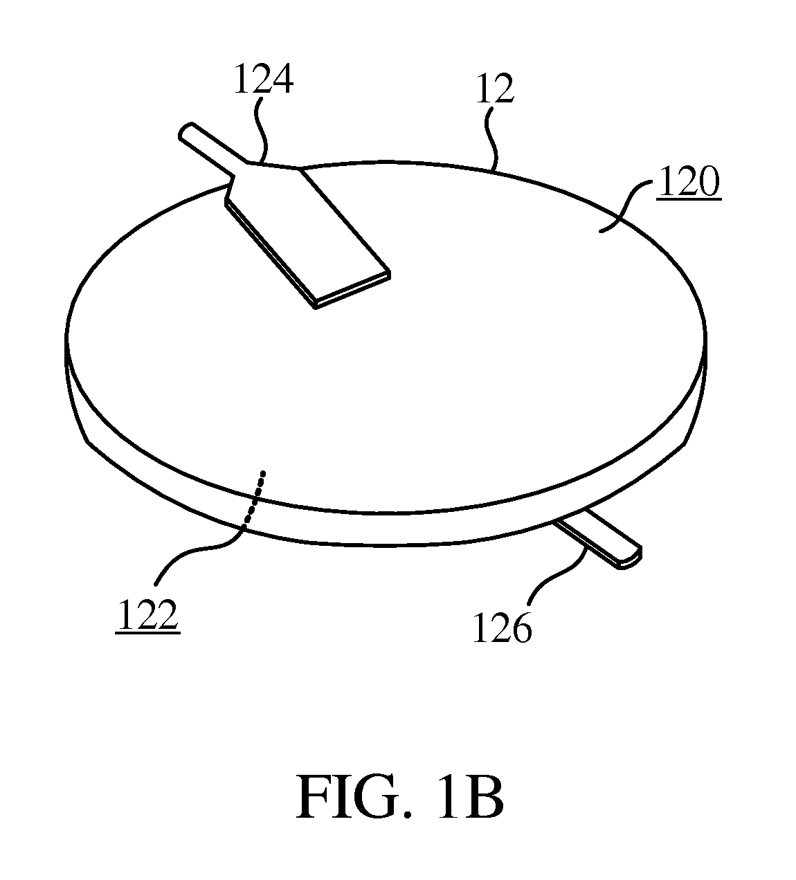
[0019]Please refer to FIG. 1A. FIG. 1A is a schematic diagram illustrating the control circuit device 1 according to an embodiment of the invention. According to some embodiments of the invention the control circuit device 1 comprises a lighting unit 10, battery 12, insulating sheet 14, triggering slice 16 and control module 18. ...


PUM


Abstract

A control circuit device includes a lighting unit, a battery, an insulating sheet, a triggering slice, and a control module. The insulating sheet is configured on a first electrode of the battery and forms an opening. A fixed portion of the triggering slice is configured on the insulating sheet, while a contact portion of the triggering slice extends to the opening to make contact with the first electrode through the opening by pressing the triggering slice. A first control unit of the control module is connected to the first electrode and second electrode of the battery, and the light unit to receive electric power from the battery and control when the light unit emits light. A second control unit of the control module is connected to the triggering slice, the second electrode, and the first control unit to receive power when the triggering slice is made in contact with the first electrode to switch on or off the first control unit.

Description

BACKGROUND OF THE INVENTION[0001]1. Field of the Invention[0002]The present invention relates to a control circuit device, more particularly, to a control circuit device that can be set on a wearable device and emit light.[0003]2. Description of the Prior Art[0004]As we move towards more convenient lifestyles, our material objects tend to improve as well. In the society we live in today, material objects are not only looked at for their functionality but their aesthetics as well. For example, designers have been setting devices that can emit light on shoes, clothing and accessories, just to make it stand out and flashy. In recent times, the most common type of control circuit devices that emit light on articles of clothing are LEDs. It is because of its rapidly improving technology and flexibility in the ways it emits light that it has become popular in creating special light patterns in apparel such as clothing or shoes.[0005]The LEDs mentioned above are controlled by a printed cir...

Claims


Application Information

Patent Timeline
Patent Type & Authority Applications(United States)
IPC IPC(8): F21L4/02H05B44/00
CPCA43B3/00F21S9/02F21Y2113/005F21Y2101/02F21V23/0442F21Y2115/10F21Y2113/13H05B45/20
Inventor TSENG, SHEN-KO
Owner TSENG SHEN KO
Why Eureka
Try Eureka