Polyaxial bone anchor with pop-on multi-thread shank, some with diametric interference fit inserts

a multi-thread, polyaxial technology, applied in the field of bone anchors, can solve problems such as inability to disassemble, and achieve the effect of improving spinal correction techniques

Inactive Publication Date: 2014-05-01
JACKSON
View PDF0 Cites 90 Cited by
  • Summary
  • Abstract
  • Description
  • Claims
  • Application Information

AI Technical Summary

Benefits of technology

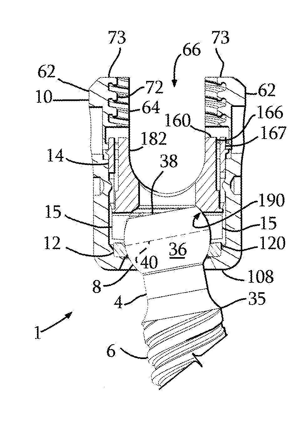
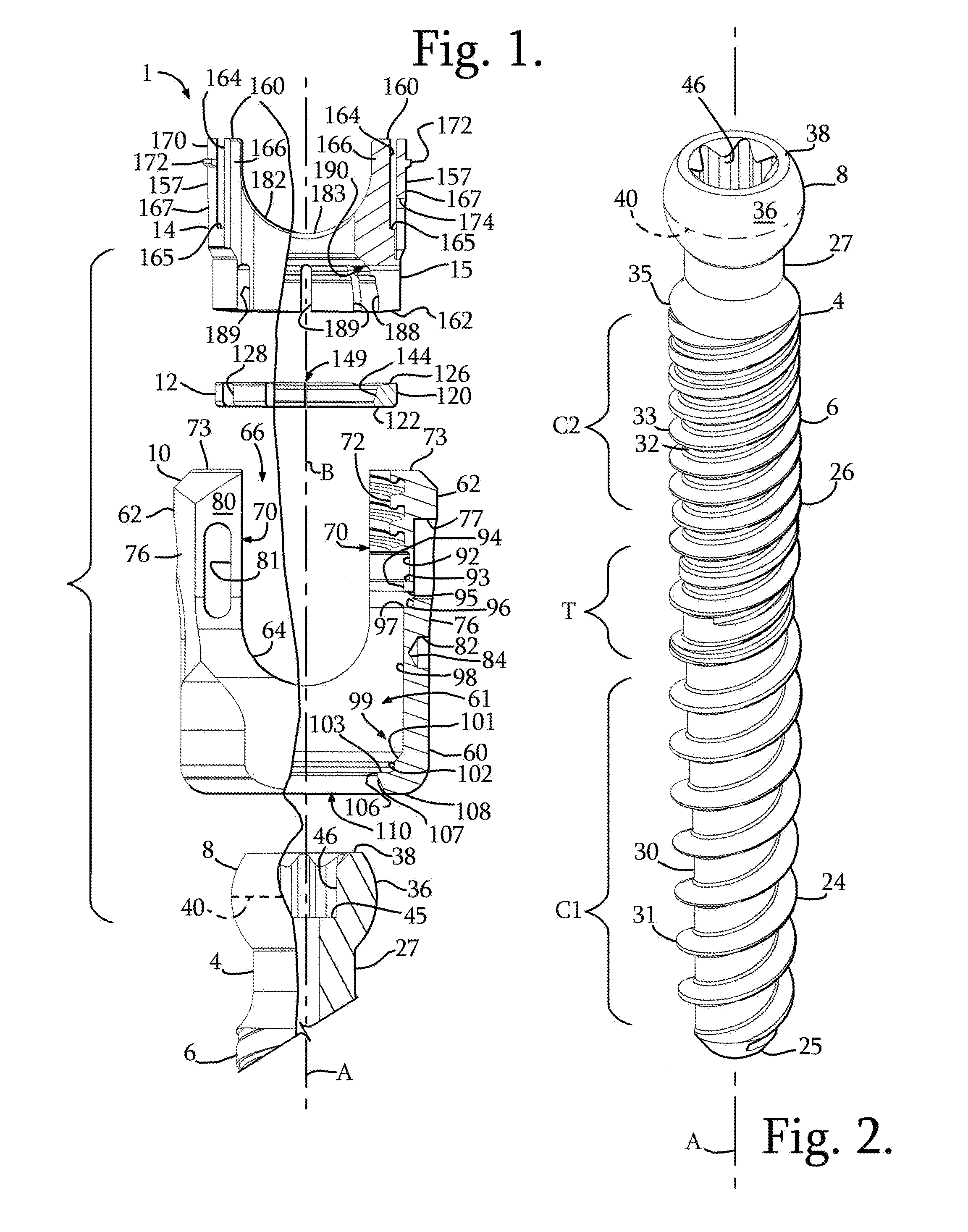
[0008]A pre-assembled receiver, compression insert and split retainer may be “pushed-on”, “snapped-on” or “popped-on” to the shank head prior to or after implantation of the shank into a vertebra. Such a “snapping on” procedure includes the steps of uploading the shank head into the receiver lower opening, the shank head pressing against the base portion of the split retainer ring, pushing the ring up against the compression insert and expanding the resilient open retainer out into an expansion portion or chamber of the receiver cavity followed by an elastic return of the retainer back to a nominal or near nominal shape thereof after the hemisphere of the shank head or upper portion passes through the retainer. In some embodiments, sometimes with the aid of tooling, the shank head enters into a friction fit engagement with a lower collet-like portion of the insert. Final fixation occurs as a result of a locking expansion-type of contact between the shank head and the split retainer and an expansion-type of non-tapered locking engagement between the retainer ring and a lower receiver portion partially defining the receiver cavity. The retainer can expand more in an upper portion or expansion chamber of the receiver cavity to allow the shank head to pass through, but has restricted expansion to retain the shank head when the retainer ring is against the surfaces defining the lower portion of the receiver cavity. The shank head is forced down against the retainer ring during final locking by the compression insert. In some embodiments, when the polyaxial mechanism is locked, opposing outer surfaces of the pressure or compression insert are forced or wedged against surfaces of the receiver resulting in a press fit or interference locking engagement, allowing for adjustment or removal of the rod or other connecting member without loss of a desired angular relationship between the shank and the receiver. This independent locking feature allows the polyaxial screw to function like a fixed monoaxial screw.
[0009]The lower pressure insert may also be configured to be independently locked by a tool or instrument, thereby allowing the pop-on polyaxial screw to be distracted, compressed and / or rotated along and around the rod to provide for improved spinal correction techniques. Such a tool may engage the insert through apertures in the receiver to force or wedge the insert down into a locked position within the receiver. With the tool still in place and the correction maintained, the rod may then be locked within the receiver channel by a closure top followed by removal of the tool. This process may involve multiple screws all being manipulated simultaneously with multiple tools to achieve the desired correction.

Problems solved by technology

Once assembled it cannot be disassembled.

Method used


Image

  • Polyaxial bone anchor with pop-on multi-thread shank, some with diametric interference fit inserts
  • Polyaxial bone anchor with pop-on multi-thread shank, some with diametric interference fit inserts
  • Polyaxial bone anchor with pop-on multi-thread shank, some with diametric interference fit inserts

Examples


Embodiment Construction

[0103]As required, detailed embodiments of the present invention are disclosed herein; however, it is to be understood that the disclosed embodiments are merely exemplary of the invention, which may be embodied in various forms. Therefore, specific structural and functional details disclosed herein are not to be interpreted as limiting, but merely as a basis for the claims and as a representative basis for teaching one skilled in the art to variously employ the present invention in virtually any appropriately detailed structure. It is also noted that any reference to the words top, bottom, up and down, and the like, in this application refers to the alignment shown in the various drawings, as well as the normal connotations applied to such devices, and is not intended to restrict positioning of the bone attachment structures in actual use.

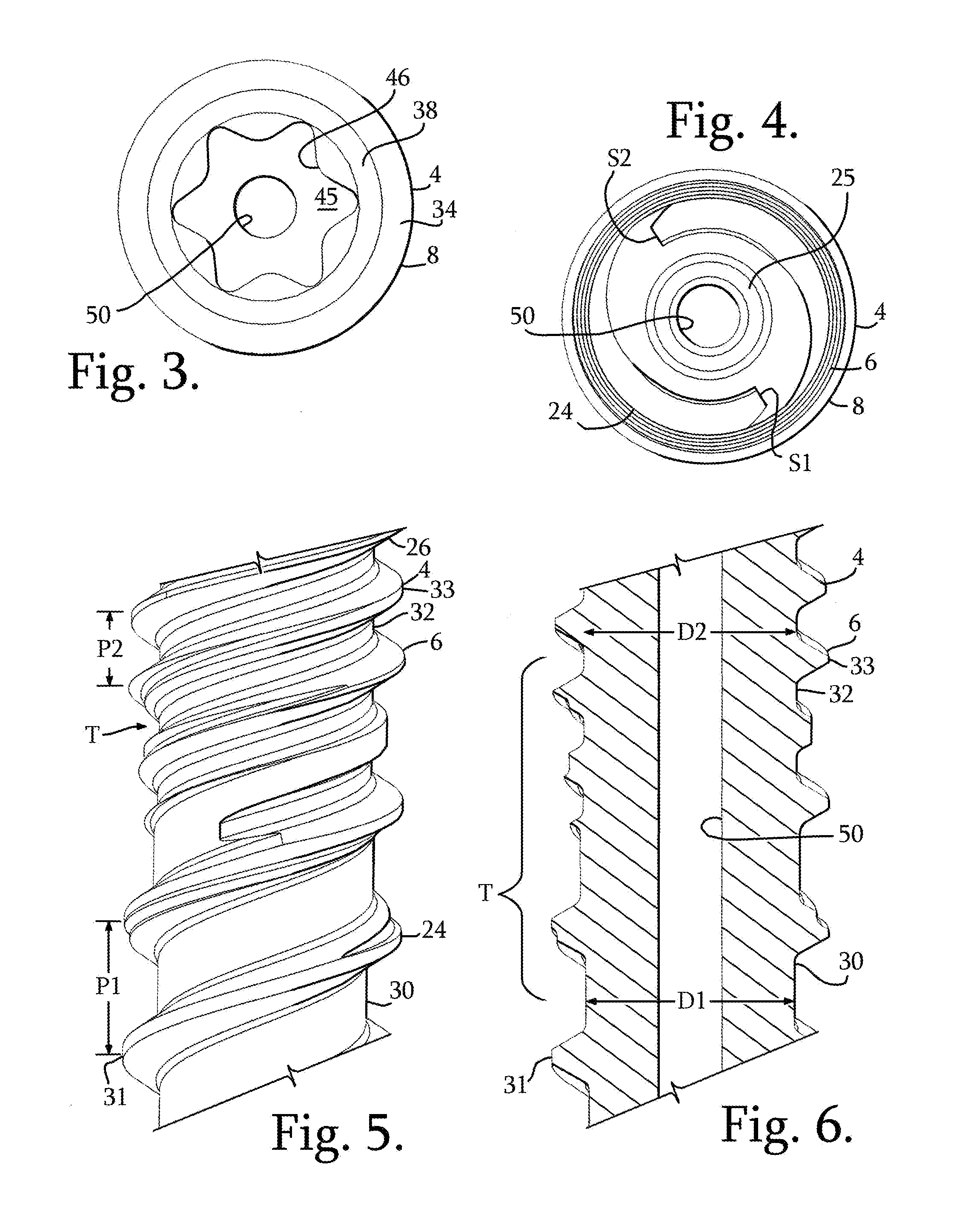
[0104]With reference to FIGS. 1-35, the reference number 1 generally represents a polyaxial bone screw apparatus or assembly according to the pres...


PUM


Abstract

Polyaxial and uni-planar bone screw assemblies include a multi-threaded shank body having an integral upper portion receivable in a one piece receiver, the receiver having an upper channel for receiving a longitudinal connecting member and a lower cavity cooperating with a lower opening. A compression insert and open retaining ring located in the receiver may be made of cobalt-chrome and the compression insert may provide a diametric interference fit with the receiver. Receivers or inserts may include resilient arm portions. The open ring cooperates with the shank to provide for pop- or snap-on assembly of the shank with the receiver either prior to or after implantation of the shank into a vertebra.

Description

CROSS-REFERENCE TO RELATED APPLICATIONS[0001]This application claims the benefit of U.S. Provisional Patent Application Ser. No. 61 / 795,984 filed Oct. 31, 2012 and U.S. Provisional Patent Application Ser. No. 61 / 851,223 filed Mar. 4, 2013, both of which are incorporated by reference herein.BACKGROUND OF THE INVENTION[0002]The present invention is directed to bone anchors for use in bone surgery, particularly spinal surgery and particularly to polyaxial and uni-planar bone screws with compression or pressure inserts and expansion lock split retainers to snap over, capture and retain the bone screw shank head in the receiver member assembly and later fix the bone screw shank with respect to the receiver assembly.[0003]Bone screws are utilized in many types of spinal surgery in order to secure various implants to vertebrae along the spinal column for the purpose of stabilizing and / or adjusting spinal alignment. Although both closed-ended and open-ended bone screws are known, open-ended...

Claims


Application Information

Patent Timeline
Patent Type & Authority Applications(United States)
IPC IPC(8): A61B17/70
CPCA61B17/702A61B17/7037A61B17/7032A61B17/863A61B17/7038
Inventor JACKSON, ROGER P.SURBER, JAMES L
Owner JACKSON
Why Eureka
Try Eureka