Control device, heating device control system, control method, program, and recording medium

a technology of control device and heating device, which is applied in the direction of lighting and heating apparatus, furniture, instruments, etc., can solve the problems of heat-up time fluctuation, waste of power of other heating zones for the purpose of temperature control, and prolonging heat-up time, so as to reduce the generation of wasted power consumption

Active Publication Date: 2014-05-08
ORMON CORP
View PDF7 Cites 3 Cited by
  • Summary
  • Abstract
  • Description
  • Claims
  • Application Information

AI Technical Summary

Benefits of technology

[0012]According to the control device according to one or more embodiments of the present invention, the generation of the wasted power consumption can be reduced even if the factor related to the fluctuation in heat-up time is generated in the heating device in which the heat-up starting time is set in each heating zone.

Problems solved by technology

Therefore, until the temperature of the heating zone having the higher setting temperature is stabilized, powers of other heating zones are wasted for the purpose of temperature control.
However, possibly the heat-up time fluctuates actually due to various factors.
Additionally, the heat-up time lengthens in the case that the heater has degraded.
Therefore, the power is consumed wastefully in the first heating zone until the second heating zone is stabilized.

Method used


Image

  • Control device, heating device control system, control method, program, and recording medium
  • Control device, heating device control system, control method, program, and recording medium
  • Control device, heating device control system, control method, program, and recording medium

Examples


first embodiment

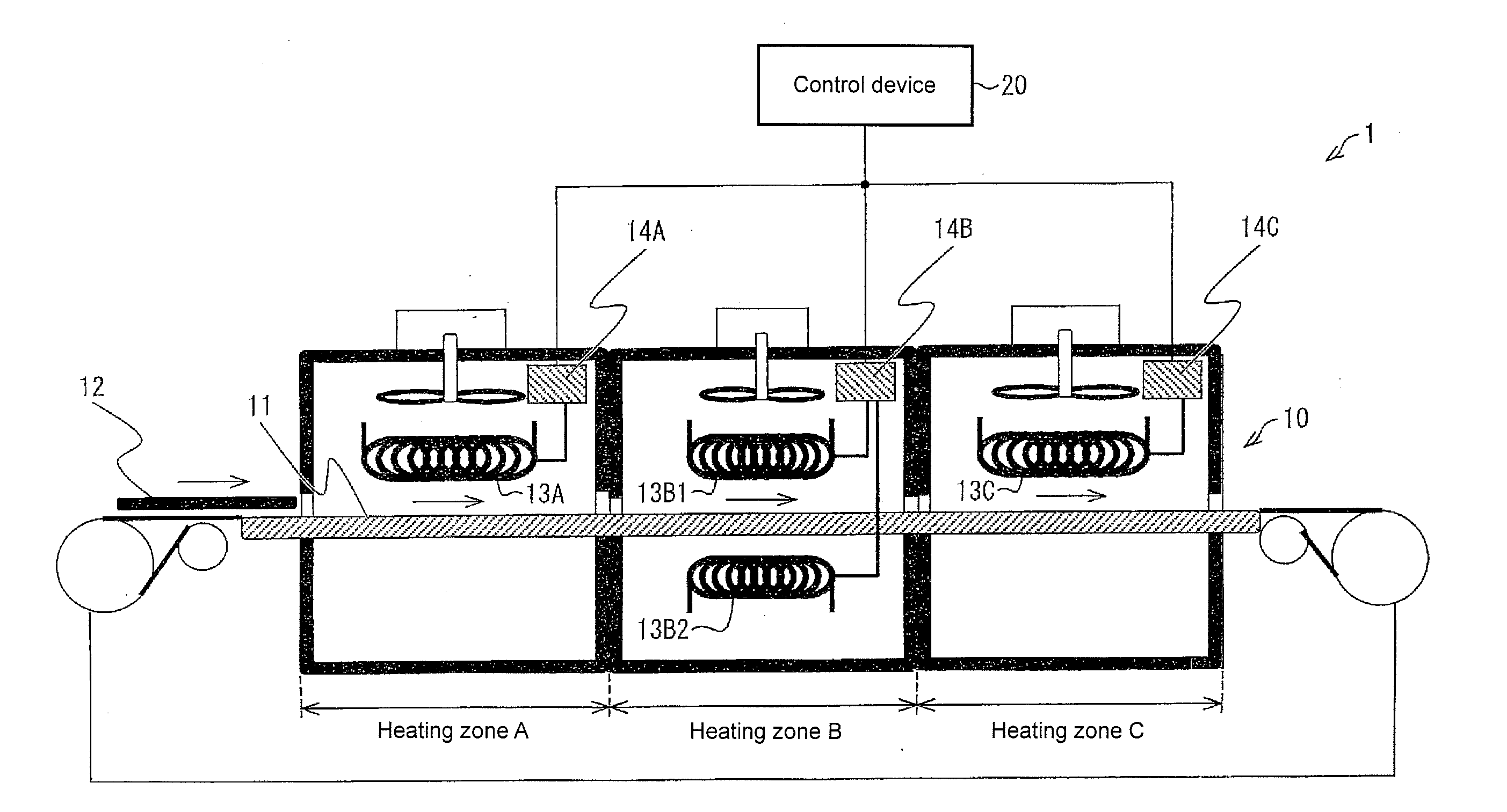
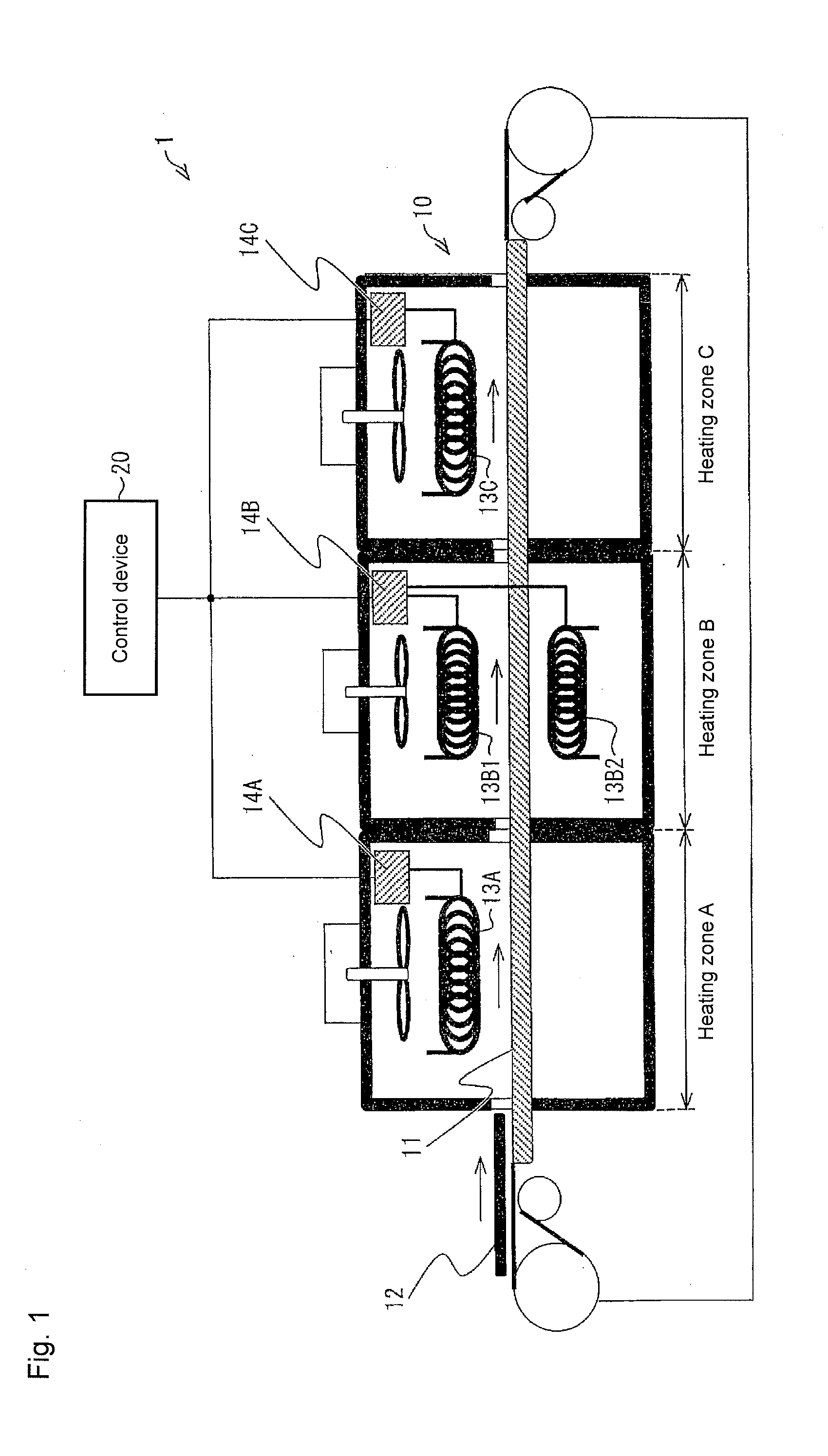
[0030]Hereinafter, embodiments of the present invention will be described with reference to the drawings. In embodiments of the invention, numerous specific details are set forth in order to provide a more thorough understanding of the invention. However, it will be apparent to one of ordinary skill in the art that the invention may be practiced without these specific details. In other instances, well-known features have not been described in detail to avoid obscuring the invention. FIG. 1 is a schematic diagram illustrating a schematic configuration of a heating device control system according to the present invention.

[0031](Configuration of Heating Device Control System)

[0032]The heating device control system 1 of the first embodiment includes a heating device 10 that heats a target object and a control device 20 that controls a heat-up starting time of the heating device 10. The heating device 10 and the control device 20 are connected to each other so as to be able to conduct co...

second embodiment

[0078]The second embodiment is the most appropriate mode in the case where the temperature of the heating zone is increased at the multiple steps. For example, in adjacent heating zones having the different final target temperatures, the heating zone (a high-temperature-side heating zone) having the higher target temperature is heated up at first, and the heating zone (a low-temperature-side heating zone) having the lower target temperature is heated up at the time the high-temperature-side heating zone comes close to the target temperature. In this case, because of a large temperature difference with the low-temperature-side heating zone in a heat-up process of the high-temperature-side heating zone, the heat escapes from the high-temperature-side heating zone to the low-temperature-side heating zone, and the high-temperature-side heating zone is not efficiently heated up. Therefore, an intermediate target temperature close to the final target temperature of the low-temperature-sid...

third embodiment

[0096]FIG. 10 is a block diagram illustrating a schematic configuration of a control device 20′ of the As illustrated in FIG. 10, the control device 20′ differs from the control device 20 in FIG. 4 in that the control device 20′ includes a correction information storage unit 25 and a threshold update unit (threshold setting unit) 26. The measured temperature acquisition unit 23 acquires the measurement clock time together with the measured temperature.

[0097]The correction information storage unit 25 stores correction information that is of the information necessary to update the threshold. Specifically, the correction information storage unit 25 stores the correction information indicating the identification number identifying the condition information concerned, the reference zone identical to the condition information concerned, the heat-up target zone identical to the condition information concerned, the target temperature (the first setting temperature) set to the reference zon...


PUM

PropertyMeasurementUnit
temperatureaaaaaaaaaa
setting temperatureaaaaaaaaaa
heataaaaaaaaaa

Abstract

A control device that controls a heating device having a plurality of heating zones, has a monitoring unit configured to monitor a temperature of at least a first heating zone in the plurality of heating zones, and a control unit configured to perform heat-up starting control, in which heat-up of at least a second heating zone is started in the plurality of heating zones, based on the temperature of the first heating zone.

Description

BACKGROUND[0001]1. Technical Field[0002]The present invention relates to control of a heating device including a plurality of heating zones.[0003]2. Related Art[0004]Conventionally, in a reflow device that is used in soldering when an electronic component is mounted on a surface of a printed circuit board, in order to heat the printed circuit board with a predetermined temperature profile, the printed circuit board is conveyed through a plurality of series-connected heating zones having different temperatures using a conveyer. A temperature controller performs on / off control of a heater provided in each heating zone, thereby adjusting the temperature of each heating zone.[0005]In the reflow device, generally the heaters and the temperature controllers of all the heating zones are simultaneously powered on to separately heat up the heating zones to different setting temperatures. Therefore, until the temperature of the heating zone having the higher setting temperature is stabilized,...

Claims


Application Information

Patent Timeline
Patent Type & Authority Applications(United States)
IPC IPC(8): G05D23/19
CPCG05D23/19B23K1/008F27D21/0014F27D2019/0003H05K3/3494F27B9/20
Inventor KAWAI, WAKAHIROBESSHO, TAKAFUMI
Owner ORMON CORP
Why Eureka
Try Eureka