
Image forming apparatus and image forming method

a technology of image forming apparatus and forming method, which is applied in the direction of electrographic process apparatus, instruments, optics, etc., can solve the problems of ineffective economic efficiency, adverse environmental effects of waste toner generation, and soil due to toner generation in work, so as to reduce the generation of waste toner

Inactive Publication Date: 2009-03-10
KK TOSHIBA +1
View PDF17 Cites 2 Cited by
  • Summary
  • Abstract
  • Description
  • Claims
  • Application Information

AI Technical Summary

Benefits of technology

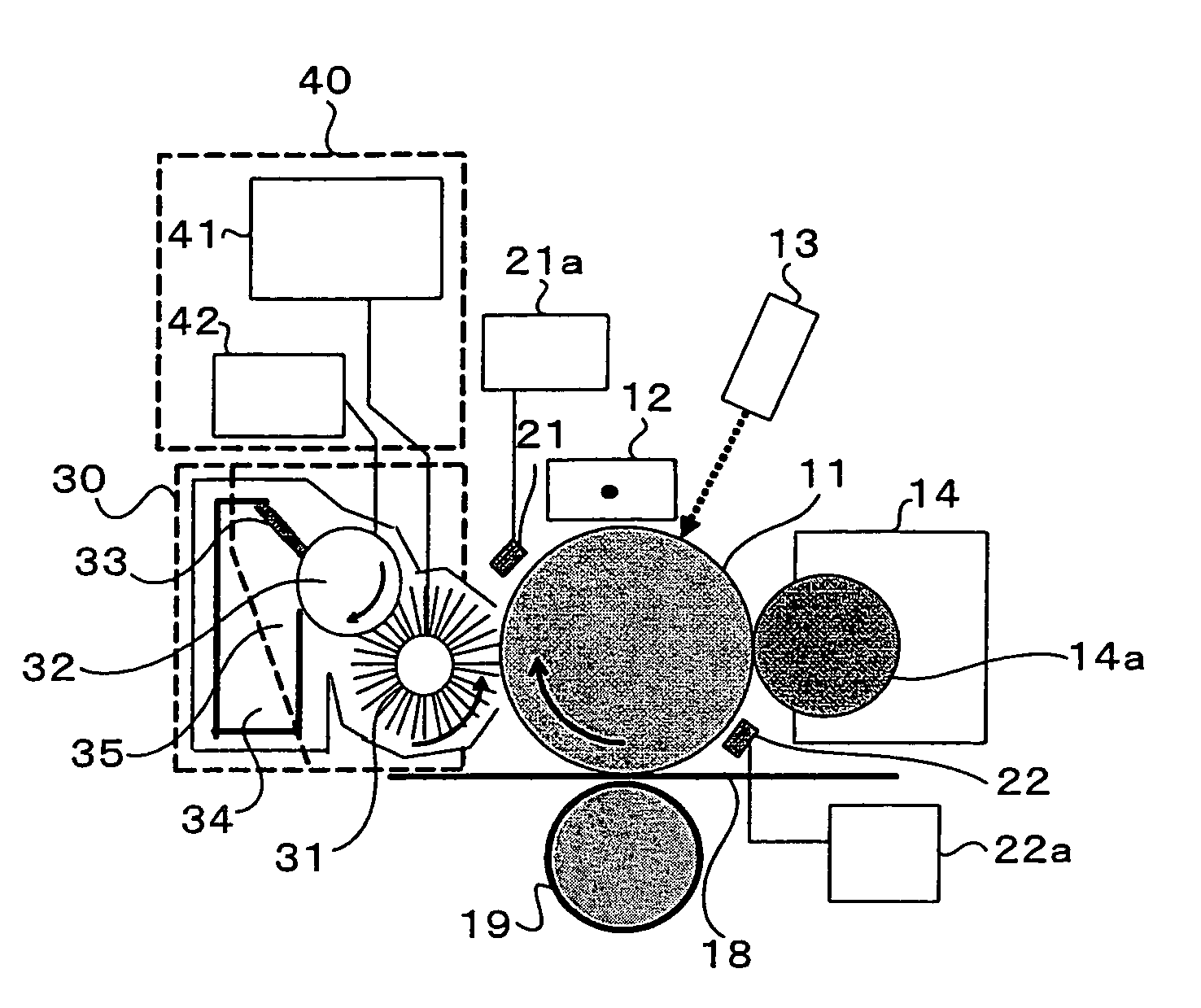
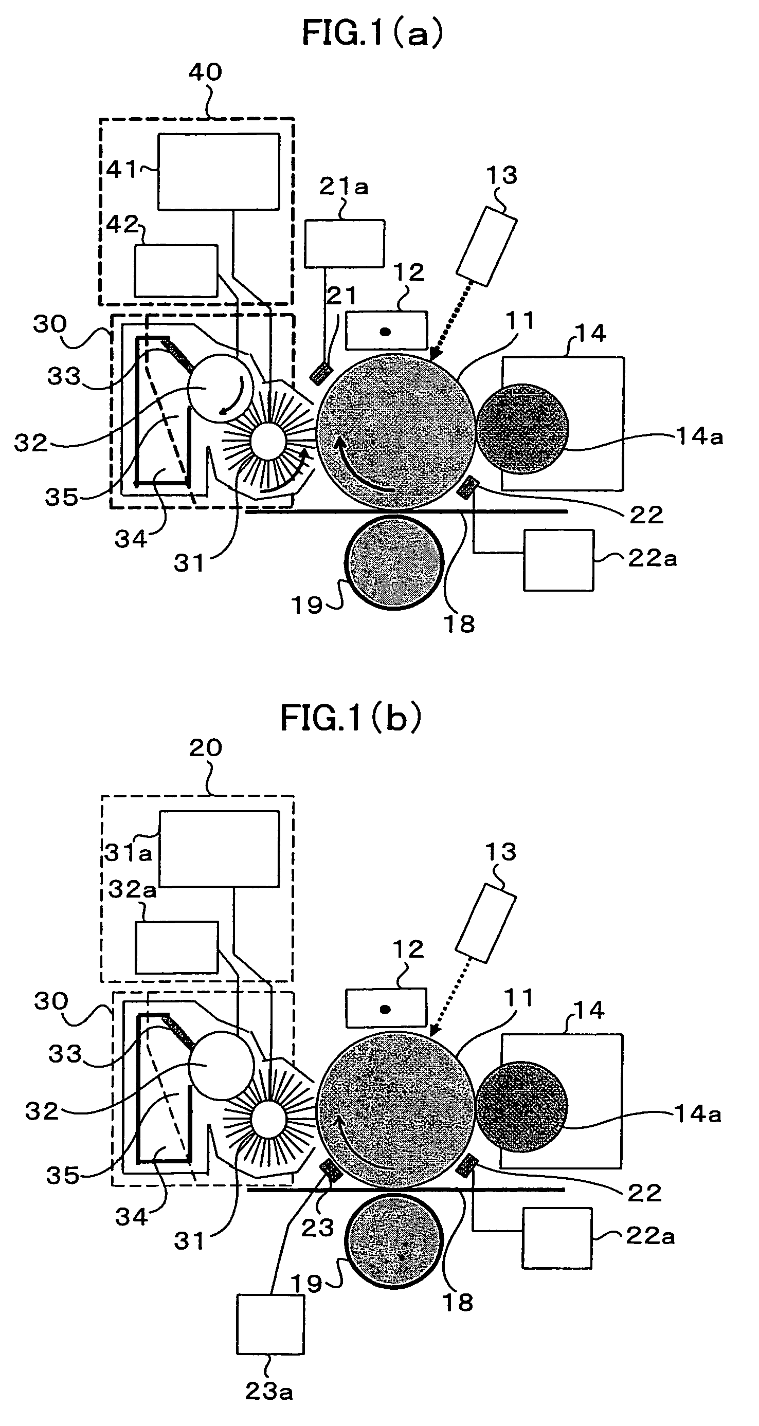
The invention aims to reduce waste toner by cleaning a part of residual toner and leaving an amount of toner in a range not hindering the next image formation on a photosensitive member. To achieve this, an image forming apparatus and method have been developed that includes a cleaner for transferring a toner image to a transfer member and removing a part of residual toner, a passing toner amount detecting unit for detecting or estimating the amount of passing toner, and a cleaner control unit for setting a target value of the amount of passing toner and controlling the cleaner accordingly. This results in a cleaner that removes only the necessary amount of residual toner, minimizing waste and improving the efficiency of the image forming process.

Problems solved by technology

When the users dispose of waste toners, it is likely that soil due to the toners occurs in the work.
Moreover, generation of wastes as waste toners adversely affects the environment and is not economically efficient.
In this way, the disposal of waste toners gives a negative image for both the users and the society in general.
However, such a cartridge system also has a problem.
As a result, cost of consumables increases.
On the other hand, in order to extend a life of the cleaner to make a replacement cycle thereof longer, a structure of the cleaner itself is inevitably complicated.
Therefore, a size of the cleaner is increased, making it difficult to apply the cleaner to a photosensitive member having a small diameter.
However, even if the cleaner is replaced in this way, when an amount of waste toner is large, frequency of replacement of the cleaner has to be increased, a size of a cleaner unit itself has to be increased, or the cleaner and a waste toner tank have to be arranged separately to replace only the waste toner tank.
Therefore, the problem described above is not still solved.
However, this system has a problem in that a high image quality is not obtained because a transfer residual toner is a hindrance at the time of exposure.
If the paper powder or the dust mixed in the transfer residual toner entirely enters a developing device, the paper powder or the dust could cause deterioration in an image quality.
Since the transfer residual toner contains a large quantity of toner with poor performance that could not eventually be transferred, if the toner is entirely collected in the developing device, like the paper powder and the like, the toner causes deterioration in an image quality later.
Thus, the method of intentionally depositing the toner on the photosensitive member is against the original form of use of the toner.
However, in this method, since only the toner inversely charged can be collected, if an amount of transfer residual toner of the regular polarity is simply large, since the toner cannot be collected by a cleaner, image memory occurs to deteriorate an image quality.

Method used


Image

  • Image forming apparatus and image forming method
  • Image forming apparatus and image forming method
  • Image forming apparatus and image forming method

Examples


examples

[0133]An experiment for checking an effect in the case in which the embodiment of the invention was carried out was attempted.

[0134]Three kinds of toners with average particle diameters of 6.5 μm, 5 μm, and 3.8 μm were used in association with a transfer residual toner of about 25 μg / cm2. Polyester was used as resin of the toner, the toner was created by the grinding method and classified, and particle diameters were adjusted using substantially the same material.

[0135]The brush roller 31 already explained was used as the cleaning means. An amount of cleaner passing toner was adjusted by changing a peripheral speed difference. In that case, in order to determine cleaning conditions, an actual amount of toner on the photosensitive member 11 that has passed the cleaner was measured by a reflectance meter.[0136](A) For example, in the case of a toner with a particle diameter of 6.5 μm, an upper limit of an amount of passing toner for not causing an image defect (FIG. 3(a)) is 16 μg / cm2...


PUM


Abstract

It is an object of the invention to provide an image forming apparatus and an image forming method that can reduce generation of a waste toner.An image forming apparatus according to the invention includes an image bearing member on which a toner image is formed, a cleaner that transfers a toner image formed on the surface of the image bearing member and, then, removes a part of a toner remaining on the image bearing member and allows the remainder to pass as a passing toner, a passing toner amount detecting unit for detecting or estimating an amount of passing toner that passes the cleaner, and a cleaner control unit that sets, on the basis of an amount of passing toner detected by the passing toner amount detecting unit, a target value of the amount of passing toner and controls a cleaning operation by the cleaner.

Description

BACKGROUND OF THE INVENTION[0001]1. Field of the Related Art[0002]The present invention relates to an image forming apparatus and an image forming method, and, more particularly to an image forming apparatus and an image forming method that can reduce a waste toner after transfer.[0003]2. Description of the Related Art[0004]In recent years, a reduction in size and improvement of an image quality of electrophotographic apparatuses have advanced and the electrophotographic apparatuses have been used in various places and applications. According to the reduction in size and the improvement of an image quality, importance of replacement work for consumables and maintenance work such as replacement of components has also been increasing. Maintenance most frequently performed by users in the electrophotographic apparatuses is replacement work for toner cartridges followed by disposal of waste toners.[0005]When the users dispose of waste toners, it is likely that soil due to the toners occ...

Claims


Application Information

Patent Timeline
Patent Type & Authority Patents(United States)
IPC IPC(8): G03G15/00
CPCG03G21/007G03G15/0856G03G2221/0005G03G15/5041
Inventor WATANABE, TAKESHITAKAHASHI, MASASHIKOUYAMA, MITSUAKI
Owner KK TOSHIBA
Learn More