Backlit Graphic Display Device with Device-to-Surface Mounts

Active Publication Date: 2014-05-15
POWERDECAL HLDG
View PDF6 Cites 22 Cited by
  • Summary
  • Abstract
  • Description
  • Claims
  • Application Information

AI Technical Summary

Benefits of technology

[0011]There is a need to enhance visibility of graphic elements in different places, for many safety reasons and marketable applications. For example, enhanced visibility of graphic elements on vehicles may help overcome low visibility driving condit

Problems solved by technology

Illumination provided by the EL lamp may be less than the illumination of background brightness

Method used


Image

  • Backlit Graphic Display Device with Device-to-Surface Mounts
  • Backlit Graphic Display Device with Device-to-Surface Mounts
  • Backlit Graphic Display Device with Device-to-Surface Mounts

Examples


Embodiment Construction

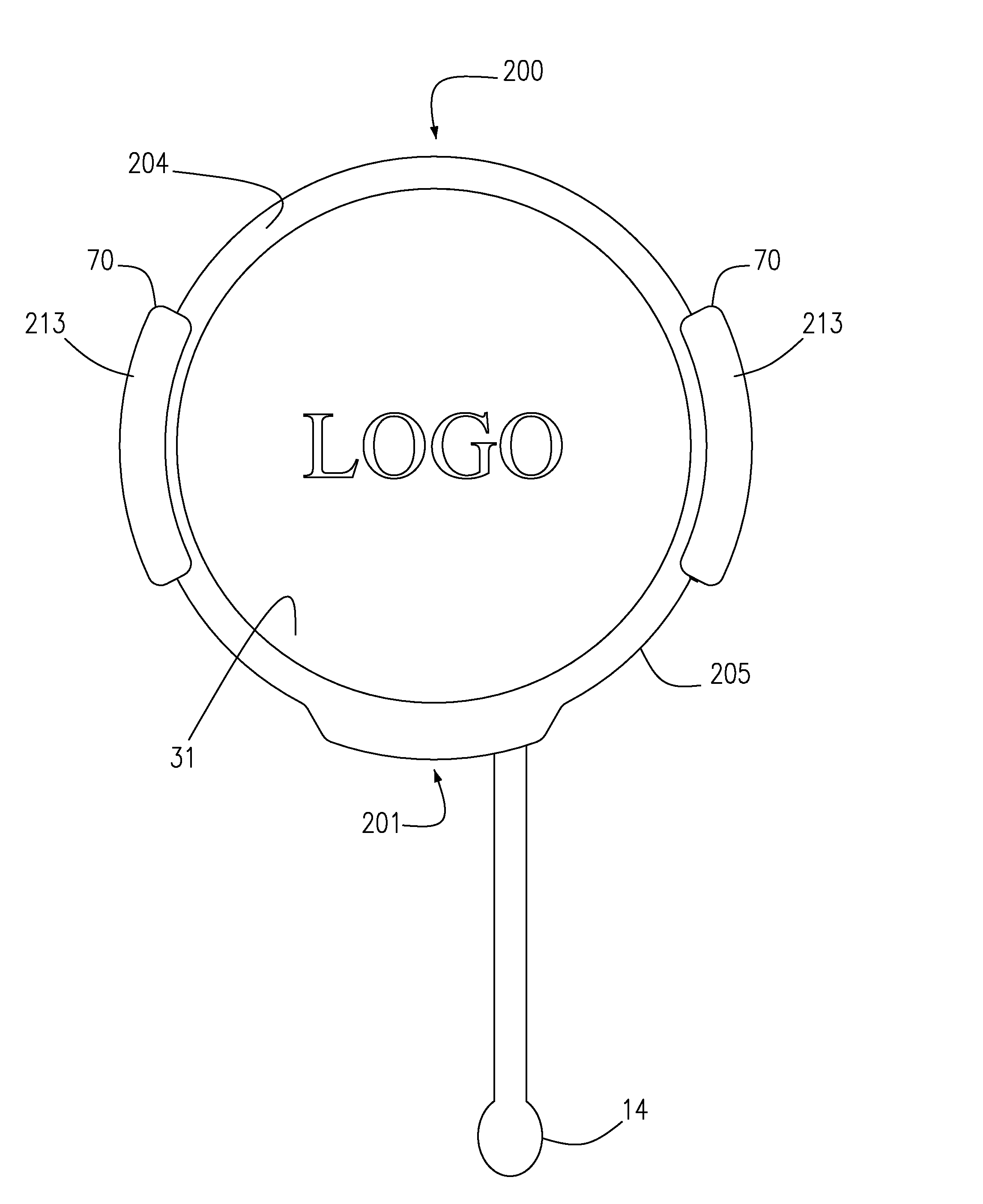
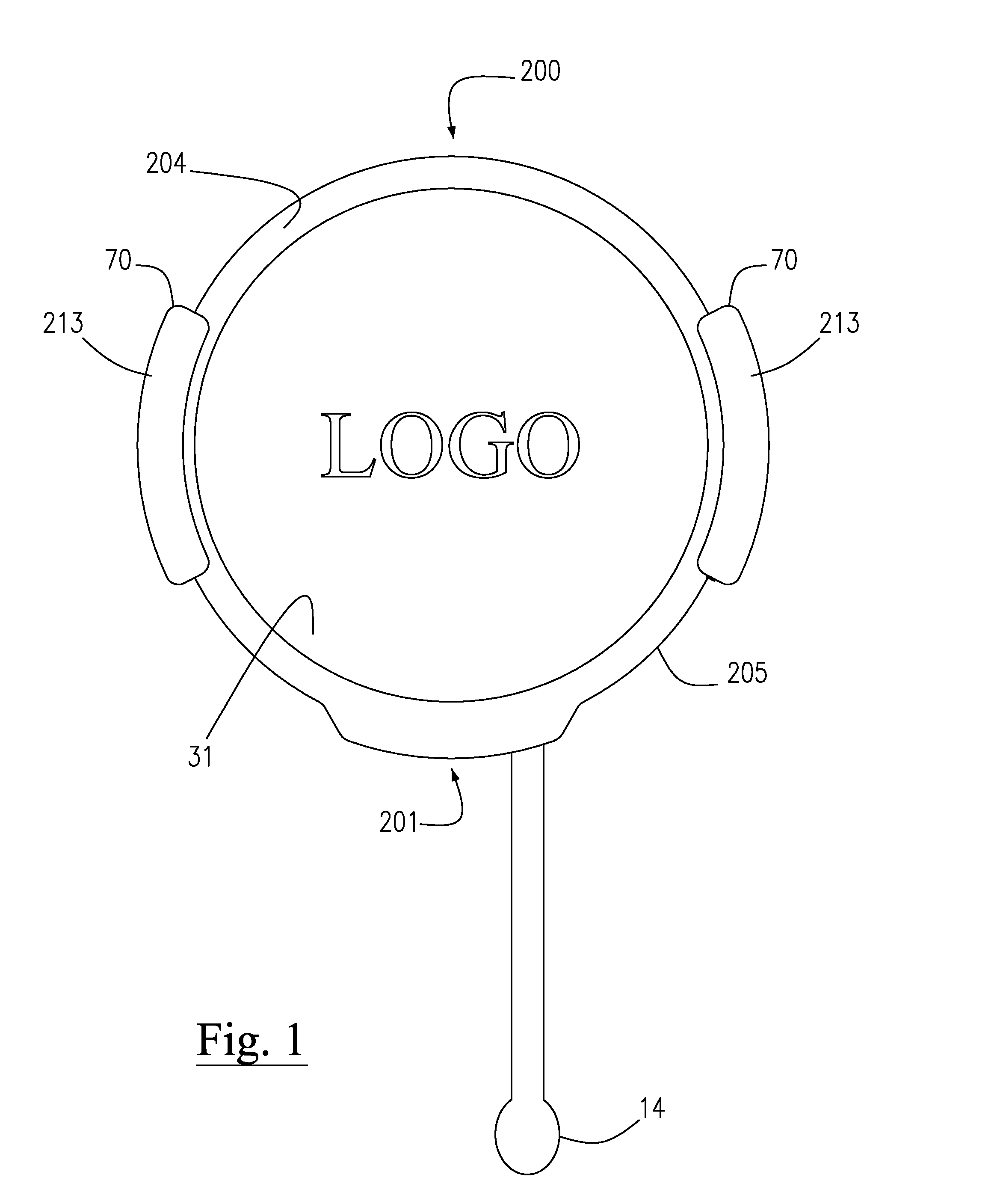
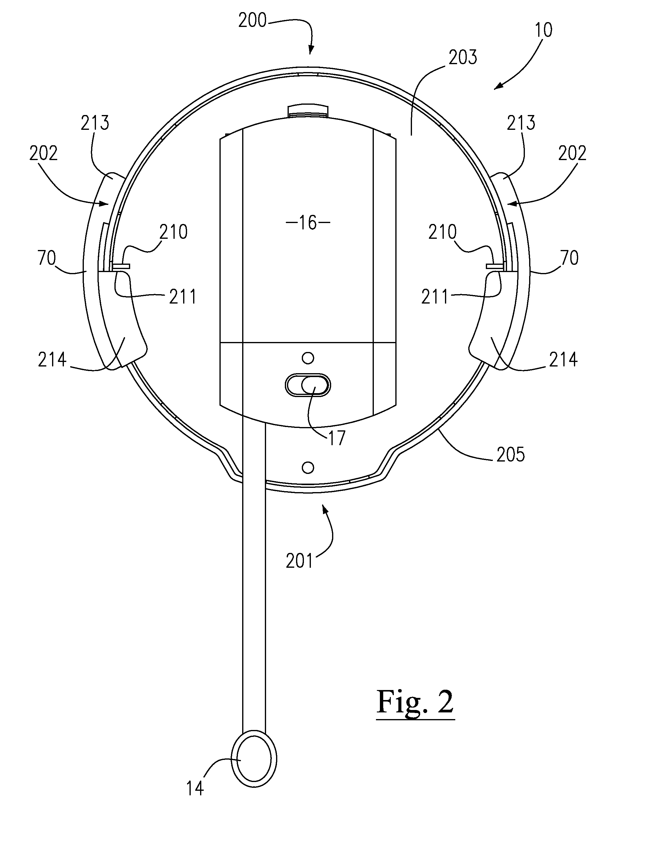
[0038]The present invention provides a backlit graphic display device as depicted and referenced at 10. The backlit graphic display device 10 according to the present invention preferably and essentially functions to illuminate interchangeable graphic panels or graphic lenses as at 31. To achieve this primary objective, the backlit graphic display device 10 according to the present invention preferably and essentially comprises a housing assembly, a light source assembly, a light guide assembly, and certain especially formed device-to-surface retainer structures or mounts as at 70.

[0039]The housing assembly preferably and essentially comprises a housing top as at 200, a housing bottom as at 201, laterally opposed housing sides as at 202, a housing back section as at 203, a housing front section as at 204, and peripheral housing edging 205 (as preferably defined by the housing front section 204). The housing edging 205 may be formed in any number of shapes, including but not limited ...


PUM


Abstract

A graphic display device illuminates interchangeable graphic panels and is mountable to a translucent mounting surface. The graphic display device includes a housing assembly, a light source assembly, a light guide assembly, and device-to-surface mounts. The housing assembly includes a housing back, a housing front, and peripheral housing edging. Together, the housing back and housing edging define a panel-receiving volume. The light source assembly includes a power source, a light source, and circuitry. A light guide of the light guide assembly is positionable within the panel-receiving volume for guiding light from the light source in an anterior direction. The device-to-surface mounts fasten the graphic display device to a translucent mounting surface, and are cooperably associated with the peripheral housing edging for supporting the housing assembly such that the light from the light source is guided in an anterior direction through the translucent mounting surface.

Description

PRIOR HISTORY[0001]This U.S. patent application is related to and a continuation-in-part patent application of pending U.S. patent application Ser. No. 12 / 930,832 filed in the United States Patent and Trademark Office on 18 Jan. 2011 to which priority is claimed, which is related to and a continuation-in-part patent application of abandoned U.S. patent application Ser. No. 12 / 927,611 filed in the United States Patent and Trademark Office on 17 Nov. 2010, which is related to and a continuation-in-part patent application of abandoned U.S. patent application Ser. No. 12 / 821,944 filed in the United States Patent and Trademark Office on 23 Jun. 2010, which is related to and a continuation patent application of abandoned U.S. patent application Ser. No. 11 / 803,722 filed in the United States Patent and Trademark Office on 15 May 2007, which is a continuation patent application of abandoned U.S. patent application Ser. No. 11 / 444,174 filed in the United States Patent and Trademark Office on...

Claims


Application Information

Patent Timeline
IPC IPC(8): G09F13/04
CPCG09F13/0404G09F9/33G09F13/04G09F13/22G09F21/04H05B47/175
Inventor POD, GEORGE O.
Owner POWERDECAL HLDG
Why Eureka
Try Eureka