Eureka AIR delivers breakthrough ideas for toughest innovation challenges, trusted by R&D personnel around the world.

Floating contact assembly for switchgear

a contact assembly and switchgear technology, applied in the field of switchgear arrangement, can solve the problem that the contact assembly of the contact insulator cannot be too large, and achieve the effect of reducing the number of contacts

Inactive Publication Date: 2014-05-15
EATON CORP
View PDF4 Cites 6 Cited by
  • Summary
  • Abstract
  • Description
  • Claims
  • Application Information

AI Technical Summary

Benefits of technology

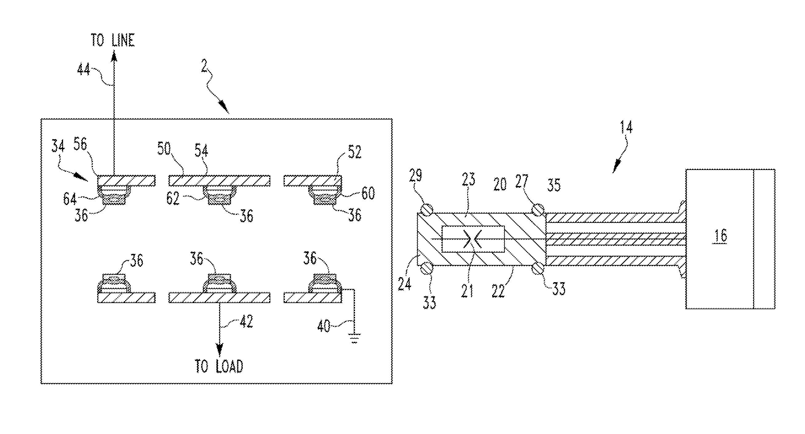
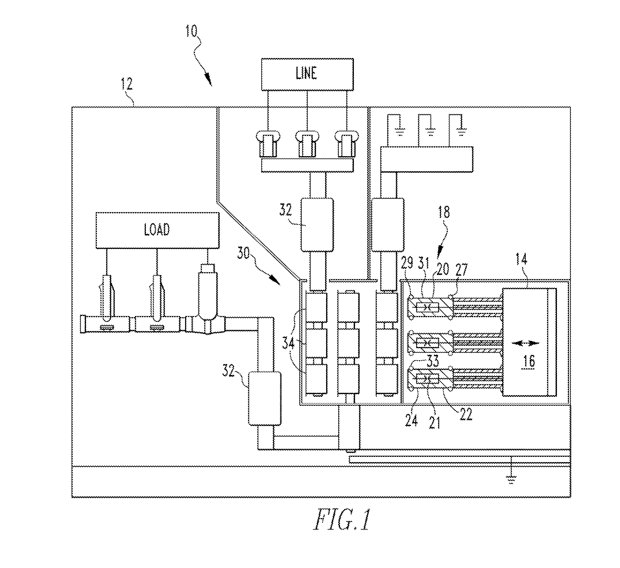
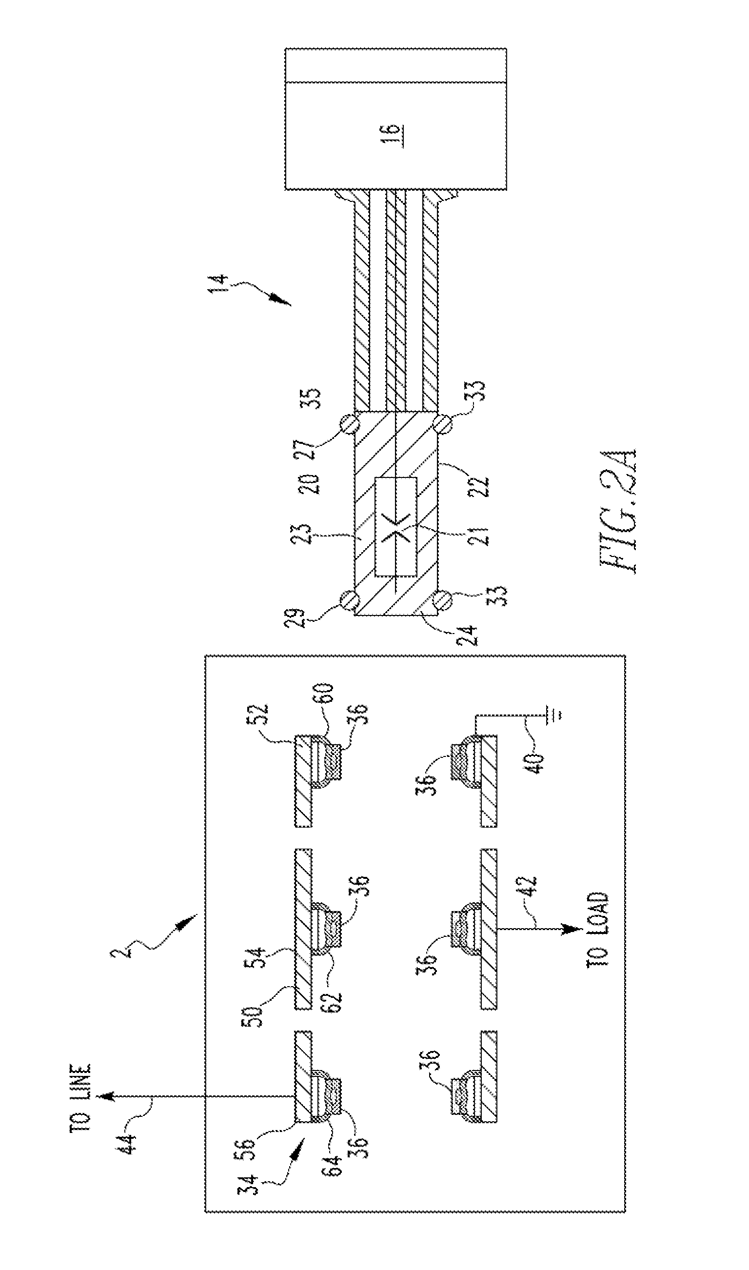
The disclosed invention relates to a floating contact assembly for electrical applications. It consists of a rigid first conductive member, a flexible conductive shunt, and a rigid second conductive member. The second conductive member "floats" within the first conductive member. This configuration may be used on either the switching element or the contact insulator. The technical effect of this invention is to provide a reliable and flexible connection between two conductive members while being movable relative to each other, which enhances the overall performance of the electrical device.

Problems solved by technology

The contact insulator contact assemblies cannot, however, be too much larger than the switching element contacts as the contacts must actually contact each other when coupled.
This is a disadvantage when the switching element is not substantially aligned with the contact insulator, i.e. when the longitudinal axis of the switching element is not substantially aligned with the longitudinal axis of the contact insulator.

Method used


Image

  • Floating contact assembly for switchgear
  • Floating contact assembly for switchgear
  • Floating contact assembly for switchgear

Examples


Embodiment Construction

[0018]As used herein, directional terms, such as, but not limited to, “forward,”“back,”“right,”“left,”“upper,”“lower,” and “lateral” correspond to the orientation of the utility cart from the perspective of a user standing at the handle portion looking toward the tray—that is, the normal position a user would occupy to move the utility cart. Such directional terms are not limiting upon the claims.

[0019]As used herein, the singular form of “a,”“an,” and “the” include plural references unless the context clearly dictates otherwise. Further, as used herein, the phrase “a number” or variations thereof means one or an integer greater than one.

[0020]As used herein, “coupled” means a link between two or more elements, whether direct or indirect, so long as a link occurs.

[0021]As used herein, “directly coupled” means that two elements are directly in contact with each other.

[0022]As used herein, “fixedly coupled” or “fixed” means that two components are coupled so as to move as one while ma...


PUM


Abstract

A floating contact assembly is provided. The floating contact assembly includes a substantially rigid first conductive member, a flexible conductive shunt, and a substantially rigid second conductive member. The flexible conductive shunt is coupled to, and is in electrical communication with, the first conductive member. The second conductive member is coupled to, and is in electrical communication with, the flexible conductive shunt. In this configuration, the second conductive member “floats” within the first conductive member.

Description

BACKGROUND OF THE INVENTION[0001]1. Field of the Invention[0002]The disclosed concept relates to a switch arrangement for an electrical switchgear.[0003]2. Background Information[0004]As is well known, a switchgear is an integrated assembly of switches, circuit breakers, buses (i.e., power supply rails), fuses and other components used to isolate electrical equipment at an electrical installation, for example, an electrical power substation. A switchgear is used to both de-energize equipment to allow work to be done and to clear faults downstream of the switchgear. The switchgear is often housed in a metal housing assembly at the installation. A circuit breaker assembly includes a base and one or more elongated switching elements, such as, but not limited to, vacuum interrupters. The switching element includes an internal set of separable contacts. That is, the switching element may be open or closed as is known. Further, the switching element includes two external contacts, one at ...

Claims


Application Information

Patent Timeline
Patent Type & Authority Applications(United States)
IPC IPC(8): H01H9/00H02B11/02
CPCH02B11/28H02B11/12H01H31/22H01H1/5822H02B11/04H02B11/02H01H1/226H01H9/00
Inventor LECCIA, BRAD, ROBERT
Owner EATON CORP
Why Eureka
Eureka Blog
Learn More