
Methods and apparatuses for a cooking device

a technology of cooking device and cooking method, which is applied in the direction of temperature measurement in household appliances, domestic stoves or ranges, instruments, etc., can solve the problems of both possible mechanical damage and exposure to soiling, and the problem of possible soiling still remains unsolved thereby, so as to achieve the effect of minimal additional expenditur

Inactive Publication Date: 2014-05-22
E G O ELEKTRO GERAETEBAU GMBH
View PDF12 Cites 23 Cited by
  • Summary
  • Abstract
  • Description
  • Claims
  • Application Information

AI Technical Summary

Benefits of technology

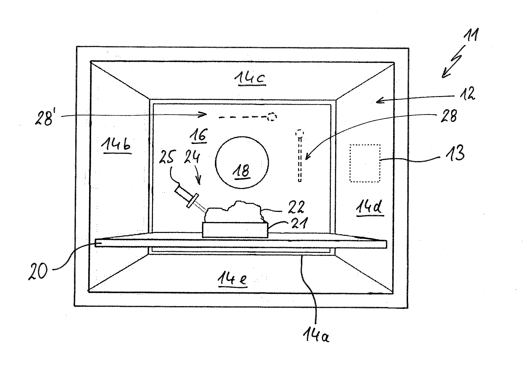
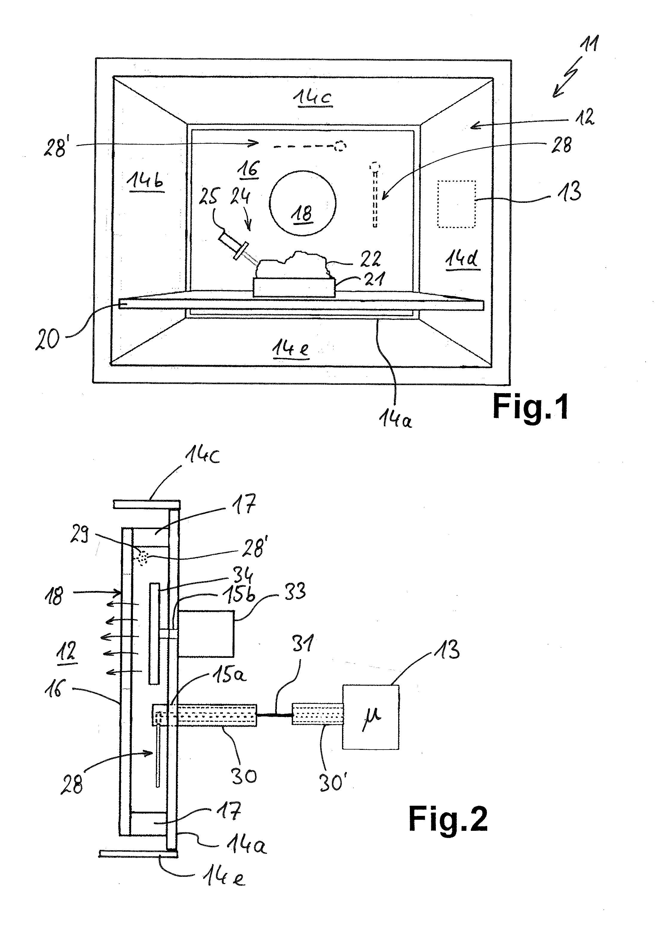
The invention describes a cooking device with an antenna for wireless signal connection to a measuring arrangement. The antenna is protected against soiling and mechanical damage by being placed between the fan plate and the cooking chamber wall. The antenna can be held in a spacer and is sealed in a tight manner to ensure a good connection. In a modification, the antenna can also be placed laterally or above the fan plate, ensuring a high wireless signal connection. The arrangement of the antenna can also be affected by the position of the fan opening on the fan plate. The invention ensures that the antenna is well protected and can be used for effective cooking control.

Problems solved by technology

It is therefore exposed however both to soiling and potentially to mechanical damage when the baking oven is cleaned.
The problem of possible soiling still remains unsolved thereby however.

Method used


Image

  • Methods and apparatuses for a cooking device
  • Methods and apparatuses for a cooking device

Examples


Embodiment Construction

[0025]A baking oven 11 as a cooking device according to the invention is illustrated in FIG. 1 in a view from the front without a door. The baking oven 11 comprises a cooking chamber 12, usually also referred to as a cavity or muffle, and also a controller 13 illustrated schematically. The cooking chamber 12 is formed by cooking chamber walls 14, wherein a cooking chamber wall 14a forms a rear face, a cooking chamber wall 14b forms a left side, and a cooking chamber wall 14d forms a right side. The upper face is formed by a cooking chamber wall 14c, and the lower face is formed by a cooking chamber wall 14e. It can be seen, in particular also from the side view in FIG. 2, that a fan plate 16 is installed in front of the rear cooking chamber wall 14a and can also be considered as an air-guiding plate.

[0026]It can be seen that the fan plate 16, at the sides, is not quite as large as the cooking chamber wall 14a or does not obscure it completely. The air-guiding plate may also be direc...


PUM

PropertyMeasurementUnit
lengthaaaaaaaaaa
lengthaaaaaaaaaa
lengthaaaaaaaaaa

Abstract

A cooking device, in particular a baking oven, includes a cooking chamber having cooking chamber walls and also a fan opening into the cooking chamber. This fan opening is provided on a fan plate fitted in front of a cooking chamber wall, an antenna being provided for wireless signal transmission with a measuring arrangement which is located in the cooking chamber and has a transceiving antenna. The antenna is arranged between the fan plate and cooking chamber wall and is thus covered or inwardly protected.

Description

CROSS-REFERENCE TO RELATED APPLICATIONS[0001]This application claims priority to German Application No. 10 2012 221 015.6, filed Nov. 16, 2012, the contents of which are hereby incorporated herein in its entirety by reference.TECHNOLOGICAL FIELD[0002]The invention relates to a cooking device, in particular a baking oven, comprising a cooking chamber, which is formed by cooking chamber walls.BACKGROUND[0003]It is known from DE 102005046012 B3 to provide a temperature probe in a baking oven as cooking device, the temperature probe having its own antenna, which communicates wirelessly with a further antenna, which is installed fixedly in the baking oven. Here, this antenna of the baking oven is arranged just below the muffle ceiling between windings of a tubular heating element as a heater for the baking oven. It is therefore exposed however both to soiling and potentially to mechanical damage when the baking oven is cleaned.[0004]A similar baking oven is known from DE 102007043370 B3....

Claims


Application Information

Patent Timeline
Patent Type & Authority Applications(United States)
IPC IPC(8): G01K1/02
CPCF24C7/085G01K2207/06G01K1/024
Inventor BELLM, MATHIAS
Owner E G O ELEKTRO GERAETEBAU GMBH
Learn More