Light emitting device

Active Publication Date: 2014-05-22
NICHIA CORP
View PDF1 Cites 10 Cited by
  • Summary
  • Abstract
  • Description
  • Claims
  • Application Information

AI Technical Summary

Benefits of technology

[0009]According to the present invention, a light emitting device can be provided which can p

Problems solved by technology

However, in the light emitting device described in JP 2005-322937A, there is a problem in that, for example, when the light emitti

Method used


Image

  • Light emitting device
  • Light emitting device
  • Light emitting device

Examples


Example

[0016]Next, embodiments of the invention will be described with reference to the drawings. In the description of the drawings below, the same or similar components are denoted by the same or similar reference symbols. However, it should be noted that the drawings are drawn schematically, and the dimensional ratios and the like of the components may differ from the actual ratios. Accordingly, the specific dimension and the like should be determined in consideration of the description below. In addition, the drawings may also include the components that have different dimensional relations and ratios among one another.

Structure of Light Emitting Device 100

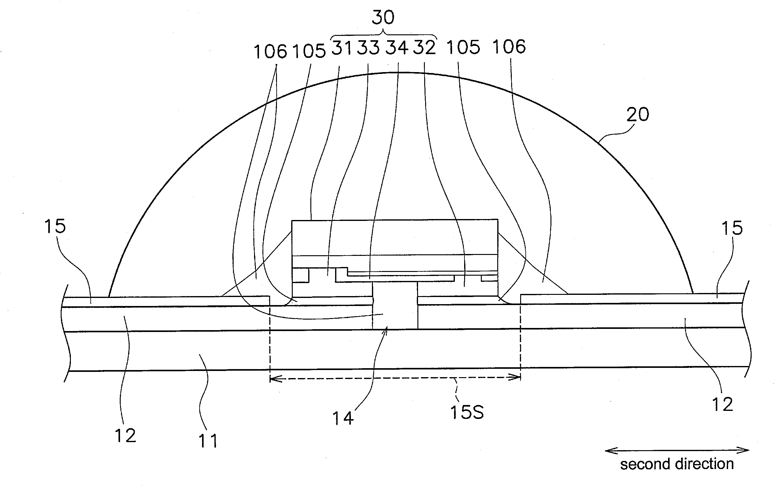
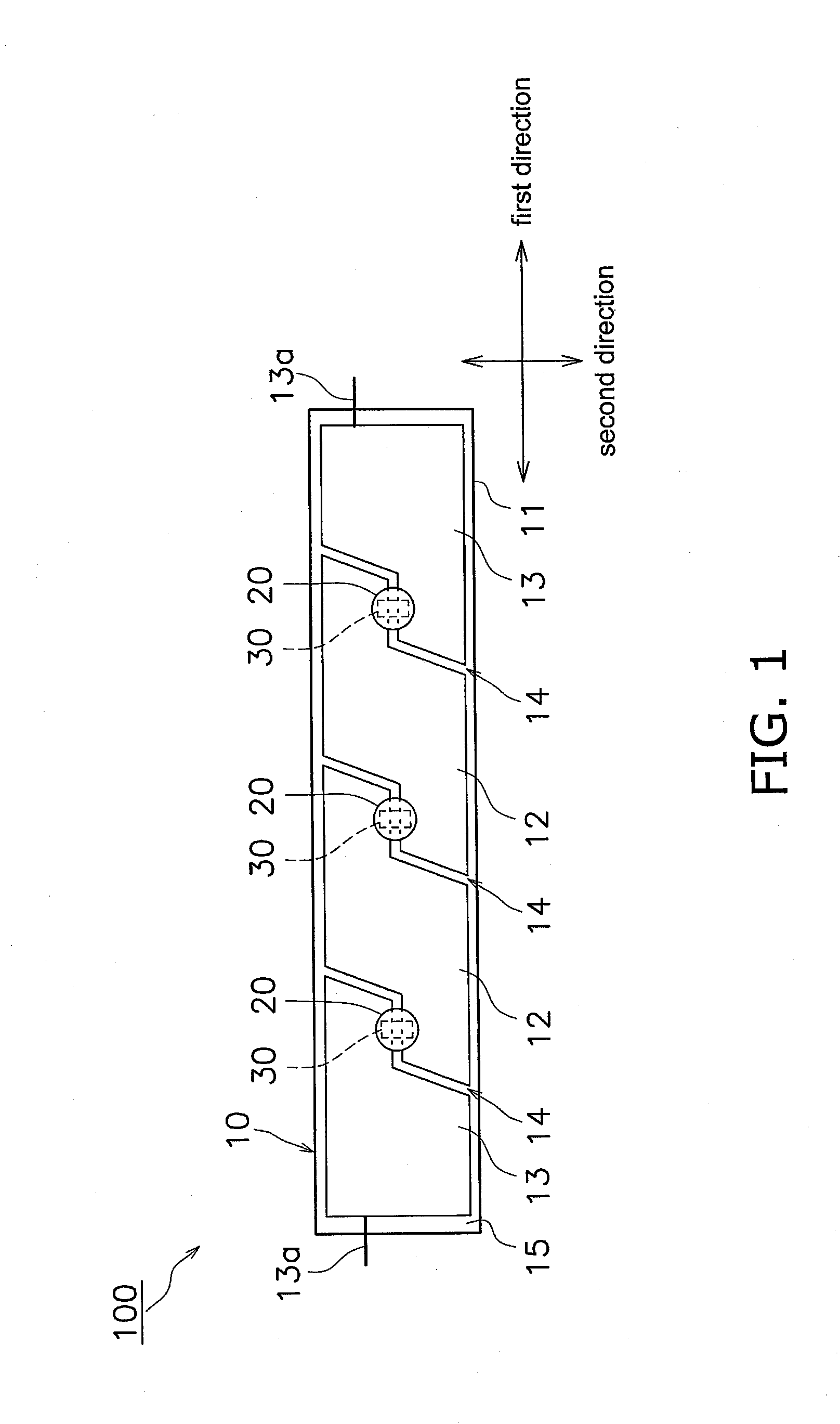
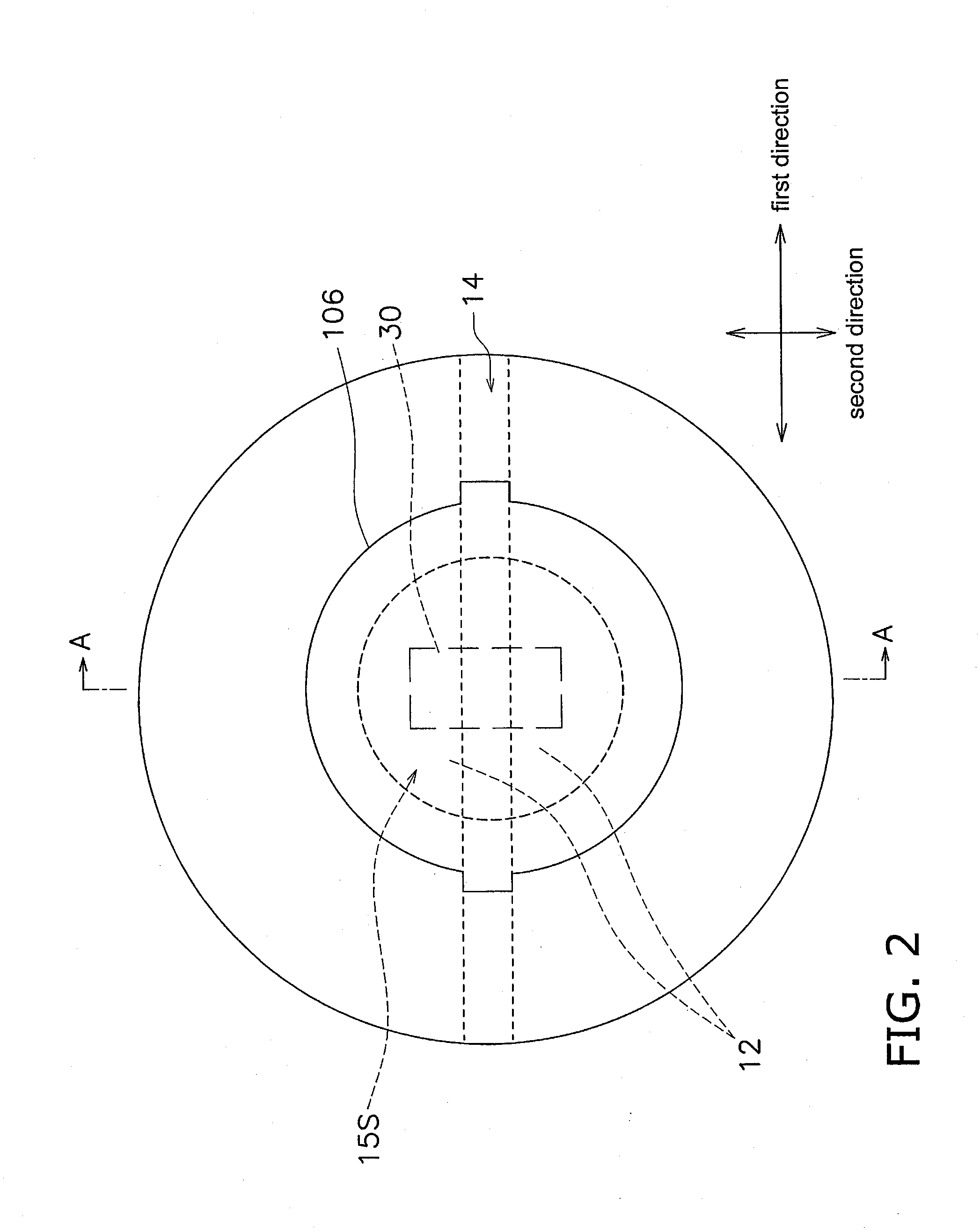
[0017]A structure of a light emitting device 100 according to an embodiment will be described with reference to the drawings. FIG. 1 is a plan view showing a structure of a light emitting device 100. FIG. 2 shows an enlarged plan view of a sealing member 20. FIG. 3 is a cross sectional view taken along line A-A of FIG. 2.

[0018]The li...


PUM


Abstract

A light emitting device includes a substrate member and at least one light emitting element. The substrate member has a groove portion defined between two wiring portions spaced apart from each other. The groove portion includes a first groove portion, a second groove portion, and a third groove portion. The first groove portion extends in a direction that forms a slanted angle with respect to a first direction, the second groove portion is spaced apart from the first groove and extends in a direction that forms a slanted angle with respect to the first direction, and the third groove portion is interconnected with the first groove portion and the second groove portion. The light emitting element is disposed over the third groove portion.

Description

CROSS-REFERENCE TO RELATED APPLICATION[0001]This application claims priority to Japanese Patent Application No. 2012-252211, filed on Nov. 16, 2012. The entire disclosure of Japanese Patent Application No. 2012-252211 is hereby incorporated herein by reference.BACKGROUND OF THE INVENTION[0002]1. Field of the Invention[0003]The present invention relates to a light emitting device which includes a substrate member and at least one light emitting element.[0004]2. Description of the Related Art[0005]There has been proposed a light emitting device which includes light emitting elements arranged on a flexible substrate member (see JP2005-322937A). The light emitting device described in JP2005-322937A can be rolled up during the transportation, and also can be cut in a desired size for use.SUMMARY OF THE INVENTION[0006]However, in the light emitting device described in JP 2005-322937A, there is a problem in that, for example, when the light emitting device is bent, concentration of stress ...

Claims


Application Information

Patent Timeline
IPC IPC(8): F21V21/14
CPCF21V21/14H01L2224/16225H01L2224/32225H01L2224/73204H01L25/0753H01L33/62H01L2924/00
Inventor MARUTANI, YUKITOSHI
Owner NICHIA CORP
Why Eureka
Try Eureka