Ceramic Matrix Composite Liner Attachment

a technology of ceramic matrix and composite liner, which is applied in the direction of machines/engines, mechanical equipment, liquid fuel engines, etc., can solve the problems of damage to ceramic matrix composite liner, difficulty in adequately mounting these liners,

Active Publication Date: 2014-05-29
RTX CORP
View PDF3 Cites 17 Cited by
  • Summary
  • Abstract
  • Description
  • Claims
  • Application Information

AI Technical Summary

Benefits of technology

[0022]In another embodiment according to any of the previous embodiments, the hanger is be attached to the support structure by a self-locking bolt and nut. A flanged washer is captured between the self-locking bolt and nut, and within an aperture in the support structure, and an aperture in the hanger bracket. The flanged washer allows adjustment of the mount bracket relative to the support structure.

Problems solved by technology

The liners are often formed of a ceramic matrix composite material, and it has been difficult to adequately mount these liners in the past.
However, this connection has sometimes resulted in damage to the ceramic matrix composite liners.

Method used


Image

  • Ceramic Matrix Composite Liner Attachment
  • Ceramic Matrix Composite Liner Attachment
  • Ceramic Matrix Composite Liner Attachment

Examples


Embodiment Construction

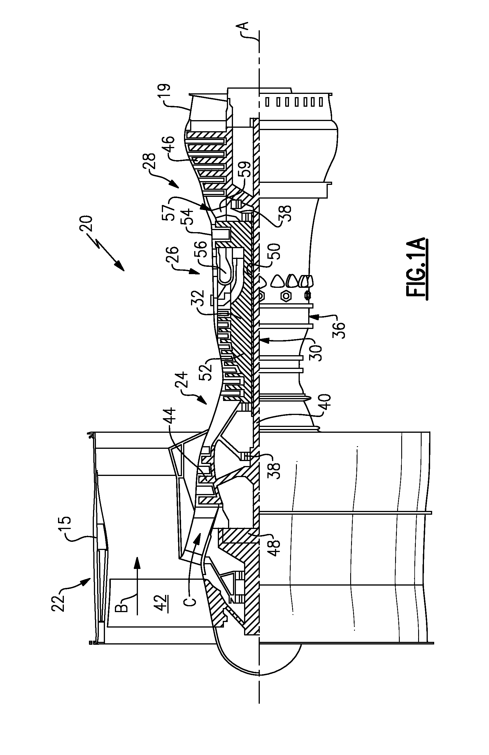
[0032]FIG. 1A schematically illustrates a gas turbine engine 20. The gas turbine engine 20 is disclosed herein as a two-spool turbofan that generally incorporates a fan section 22, a compressor section 24, a combustor section 26 and a turbine section 28. Alternative engines might include an augmentor section (not shown) among other systems or features. The fan section 22 drives air along a bypass flow path B in a bypass duct defined within a nacelle 15, while the compressor section 24 drives air along a core flow path C for compression and communication into the combustor section 26 then expansion through the turbine section 28. Although depicted as a turbofan gas turbine engine in the disclosed non-limiting embodiment, it should be understood that the concepts described herein are not limited to use with turbofans as the teachings may be applied to other types of turbine engines including three-spool architectures.

[0033]The engine 20 generally includes a low speed spool 30 and a hi...


PUM


Abstract

An attachment structure and ceramic matrix composite liner combination for a gas turbine engine has a ceramic matrix composite liner including plural flanges extending away from a face of said liner. The flanges have an opening and a bracket secured to the flanges by a securement member extending through the opening in the flange, and through an opening in the bracket. The flanges are secured to the securement member through at least one washer having a spherical face facing a spherical recess in the flanges.

Description

BACKGROUND OF THE INVENTION[0001]This application relates to a way of mounting a ceramic matrix composite liner to a support structure for use in a gas turbine engine.[0002]Gas turbine engines are known, and typically include a compressor compressing air and delivering it into a combustion section where it is mixed with fuel and ignited. Products of this combustion pass downstream over turbine rotors, driving them to rotate. The turbine rotors in turn drive compressor rotors.[0003]Downstream of the turbine rotors the products of combustion leave the engine through an exhaust nozzle. Liners are provided at the exhaust nozzle. The liners are often formed of a ceramic matrix composite material, and it has been difficult to adequately mount these liners in the past. Typically, flat washers have been utilized to secure arms on the liner to a hanger bracket, and with a bolt and pin connection.[0004]However, this connection has sometimes resulted in damage to the ceramic matrix composite l...

Claims


Application Information

Patent Timeline
Patent Type & Authority Applications(United States)
IPC IPC(8): F02C7/20
CPCF02C7/20F02K1/822F05D2240/90F05D2250/241F05D2260/30F05D2300/6033Y02T50/60
Inventor KRAMER, GEORGE J.
Owner RTX CORP
Why Eureka
Try Eureka