Circuit breaker terminal shield with position indicator

a terminal shield and circuit breaker technology, applied in the direction of protective switch details, protective switch terminals/connections, coupling device connections, etc., can solve the problems of damage to external conductors, electric couplings may become damaged, terminal screws are not in the second position, etc., to achieve the effect of being easily visible to a user

Active Publication Date: 2014-06-05
EATON INTELLIGENT POWER LTD
View PDF6 Cites 30 Cited by
  • Summary
  • Abstract
  • Description
  • Claims
  • Application Information

AI Technical Summary

Benefits of technology

[0008]When the terminal screw is in the terminal screw first position, the indicator member is in the first position, wherein the alignment surface is not aligned with the housing assembly body alignment surface. The lack of alignment between the two alignment surfaces is easily visible to a user. Thus, a user may easily determine if the terminal screw is in the first or second position.

Problems solved by technology

This may lead to a situation wherein the terminal screw is not in the second position.
For example, during installation of the circuit breaker, a user may position the external conductor in the terminal body but may choose to not tighten the terminal screw initially or may simply forget to tighten the terminal screw at that time.
If the circuit breaker is used in this configuration, the electric coupling may become damaged, overheat, damage the external conductor, may become dangerous during an over-current (fault) condition, or suffer from other detrimental effects of an external conductor that is not sufficiently biased against the terminal.

Method used


Image

  • Circuit breaker terminal shield with position indicator
  • Circuit breaker terminal shield with position indicator
  • Circuit breaker terminal shield with position indicator

Examples


Embodiment Construction

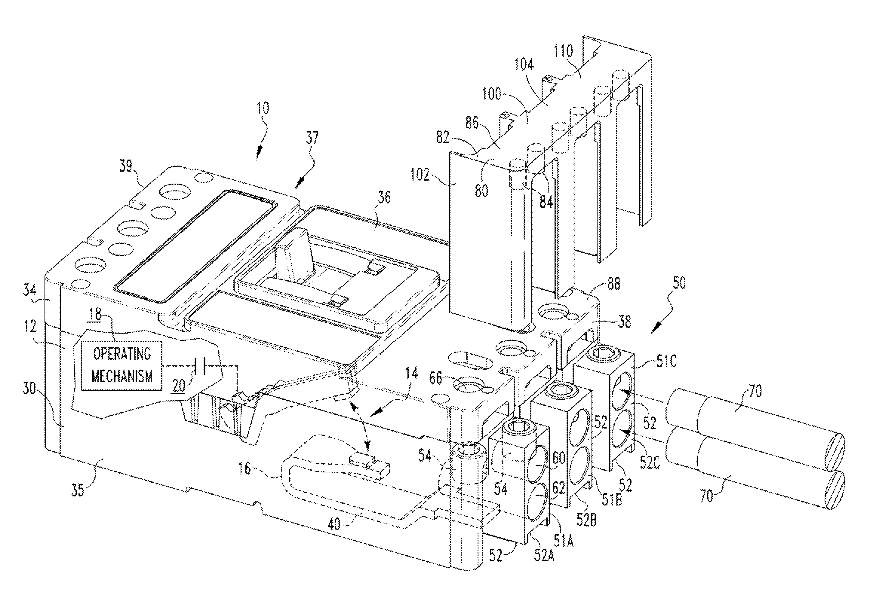
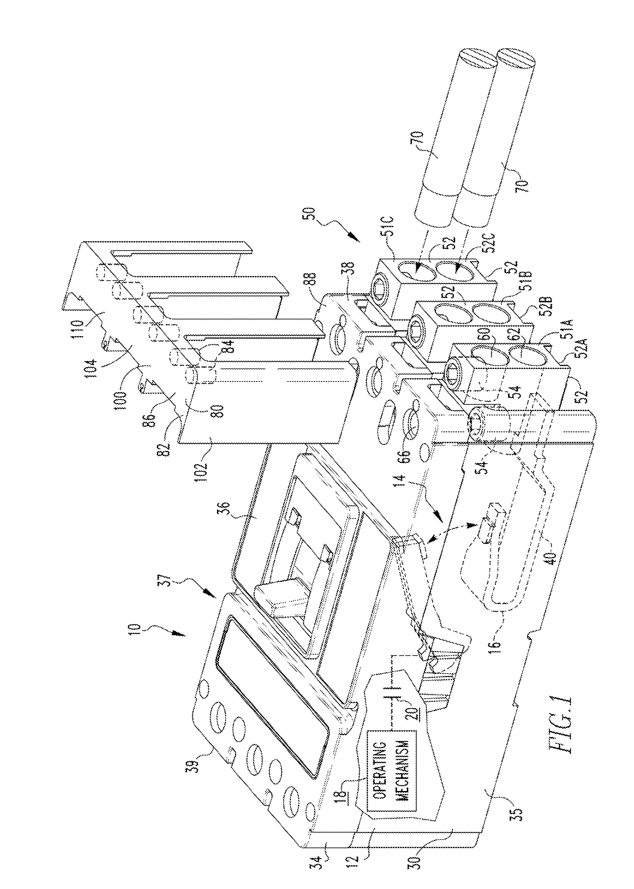
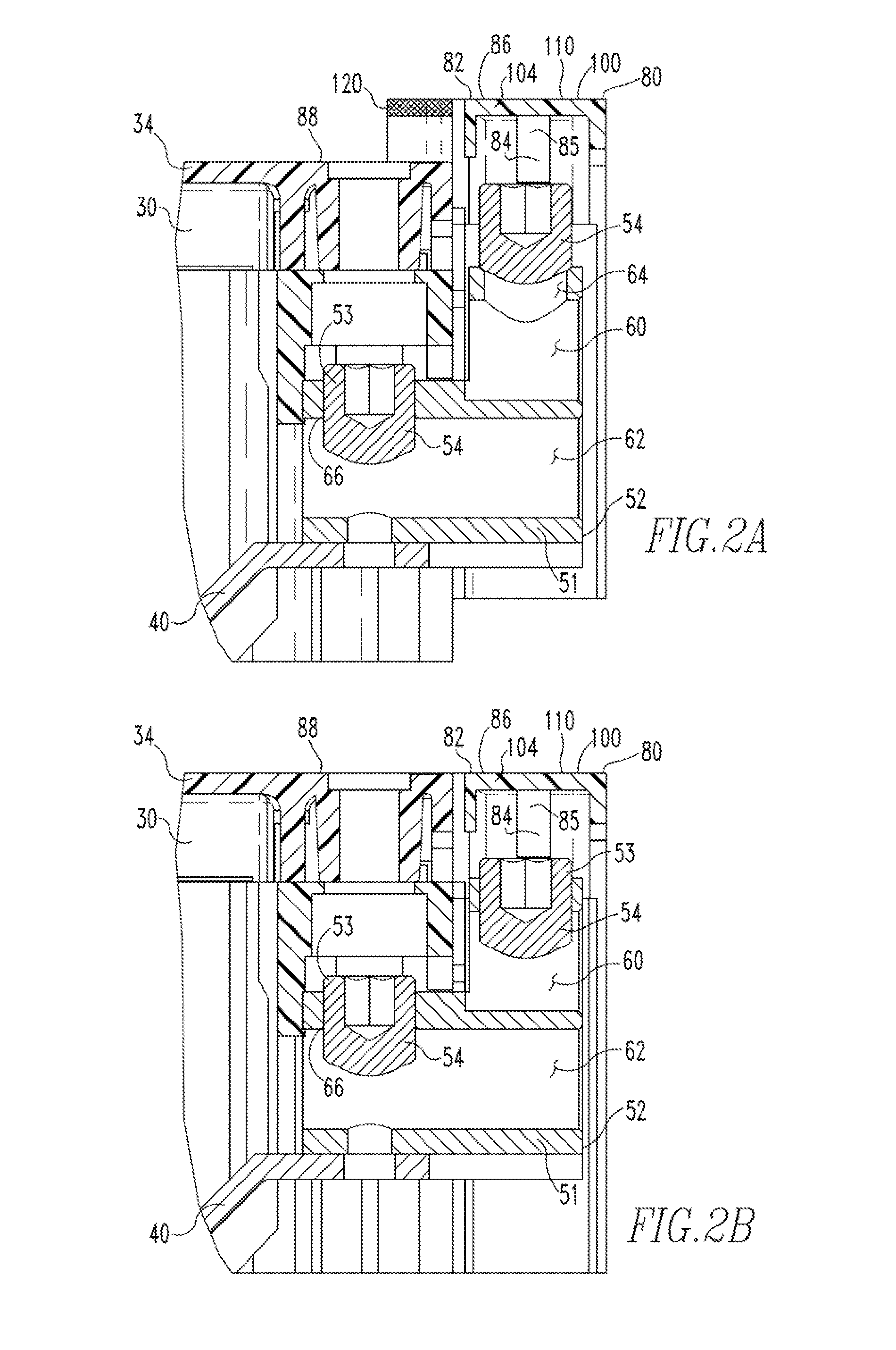
[0019]As used herein “coupled” means a link between two or more elements, whether direct or indirect, so long as a link occurs.

[0020]As used herein, “directly coupled” means that two elements are directly in contact with each other.

[0021]As used herein, “fixedly coupled” or “fixed” means that two components are coupled so as to move as one while maintaining a constant orientation relative to each other. The fixed components may, or may not, be directly coupled.

[0022]As used herein, the word “unitary” means a component is created. as a single piece or unit. That is, a component that includes pieces that are created separately and then coupled together as a unit is not a “unitary” component or body.

[0023]As used herein, the statement that two or more parts or components “engage” one another shall means that the parts exert a force against one another either directly or through one or more intermediate parts or components.

[0024]As used herein, “tightly engage” when used in reference to...


PUM


Abstract

A position indicator for a circuit breaker is provided. A circuit breaker housing assembly body has an alignment surface. The position indicator includes an indicator member having an alignment surface and an elongated spacer member. The indicator member is movably coupled to the circuit breaker housing assembly adjacent a terminal screw with the spacer member generally aligned with the terminal screw. The indicator member is structured to move between a first position, wherein the alignment surface is not aligned with the housing assembly body alignment surface, and a second position, wherein the alignment surface is aligned with the housing assembly body alignment surface. The spacer member engages the terminal screw and, if the terminal screw is in a terminal screw first position, the spacer member prevents the indicator member from moving into the indicator member second position.

Description

BACKGROUND OF THE INVENTIONField of the Invention[0001]The disclosed concept relates generally to a molded case circuit breaker and, more specifically, to a molded case circuit breaker including a terminal shield wherein the terminal shield includes a position indicator than provides a visual indication that the terminal shield is not in a seated position when the circuit breaker terminal screws are not set.BACKGROUND INFORMATION[0002]A circuit breaker, such as but not limited to a molded case circuit breaker, includes a non-conductive housing assembly that encloses a pair of separable contacts, an operating mechanism, a trip device, and other components. External to the enclosed space, the circuit breaker includes terminal, assemblies. The terminal assemblies are coupled to and in electrical communication with, conductors that extend into the enclosed space and are in electrical communication with the separable contacts. The terminal assemblies further include a conductive terminal...

Claims


Application Information

Patent Timeline
Patent Type & Authority Applications(United States)
IPC IPC(8): H01H71/02
CPCH01H71/0207H01H9/0264H01H71/08H01R4/36H01R13/447H01R13/641
Inventor SISLEY, JAMES PATRICKMALINGOWSKI, RICHARD PAULPUHALLA, CRAIG JOSEPHMCCARTHY, KELLY JULIA
Owner EATON INTELLIGENT POWER LTD
Why Eureka
Try Eureka