Fly fishing reel with drag system

a technology of reels and reels, applied in the field of fly fishing reels, can solve the problems of dragging, affecting the fishing effect, and causing the reel to “spool out”, and achieve the effect of quick removal

Active Publication Date: 2014-06-05
HEADER GREGORY A
View PDF4 Cites 9 Cited by
  • Summary
  • Abstract
  • Description
  • Claims
  • Application Information

AI Technical Summary

Problems solved by technology

This is disadvantageous because a fisherman will be forced to temporarily remove his or her hand from the crank in order to adjust the drag.
If this occurs when a fish is producing a hard run on the line, the reel is caused to “spool out” whereby excessive line is deployed by the quickly moving fish.
This will delay landing of the fish and an excessively slack line can contribute to unhooking of the fish, or snapping of the fly line leader prior to landing.
In that situation, not having an anti-reversing mechanism will result in the handle spinning backwards with great force and possibly injuring the fisherman.
Ratchet and pawl mechanisms are subject to premature wear, they lack the capacity for minute adjustment and they apply uneven torsional forces to the reel spool.
Another issue with the prior art of this type is the spool may not be removed without disassembly of the drag system and the handle crank.
Even in cases where the prior art provides friction washers for purposes of providing drag; such prior art devices do not permit quick replacement of the reel spool.

Method used


Image

  • Fly fishing reel with drag system
  • Fly fishing reel with drag system
  • Fly fishing reel with drag system

Examples


Embodiment Construction

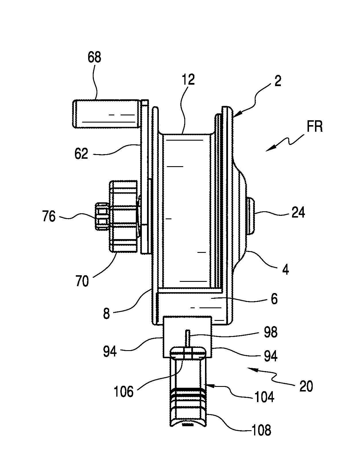
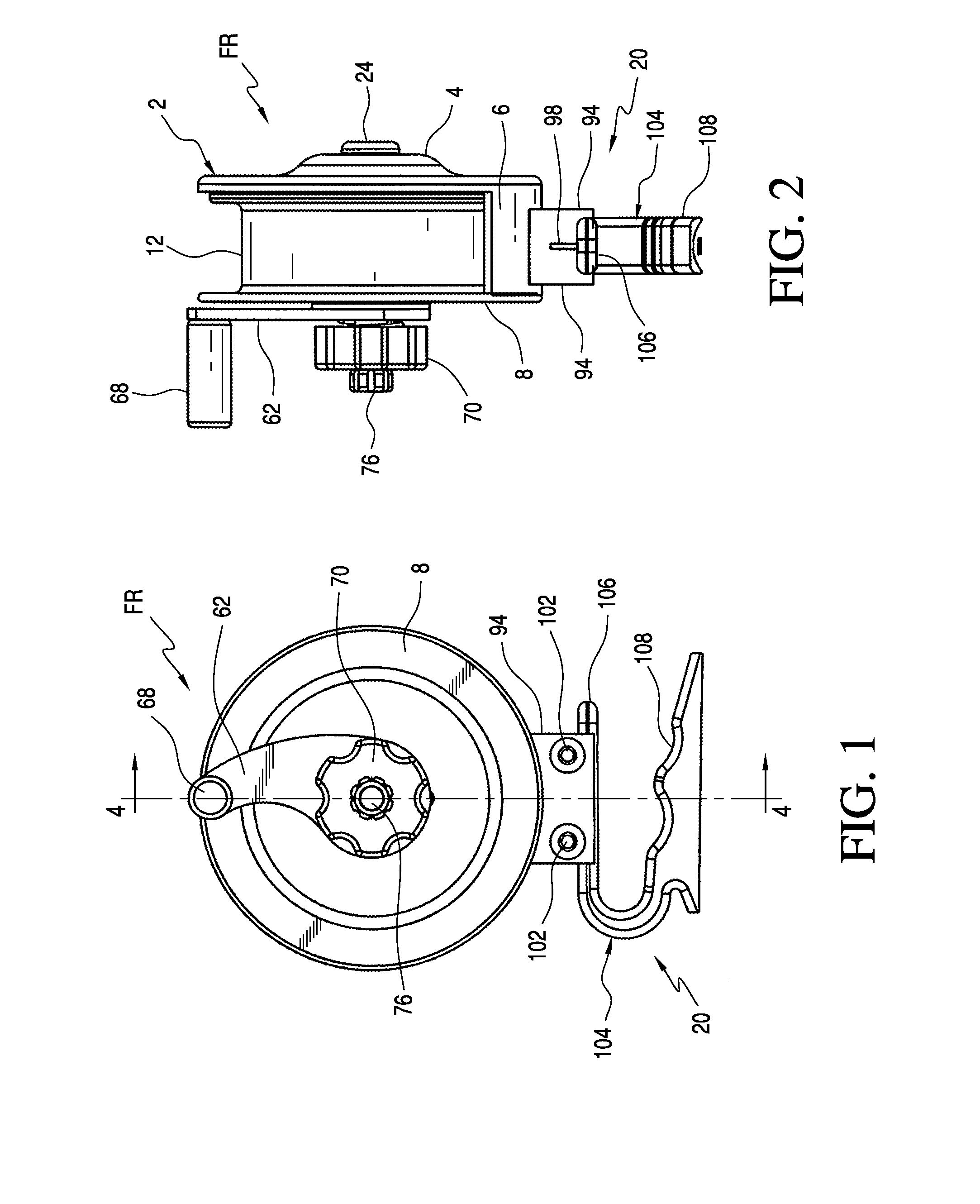
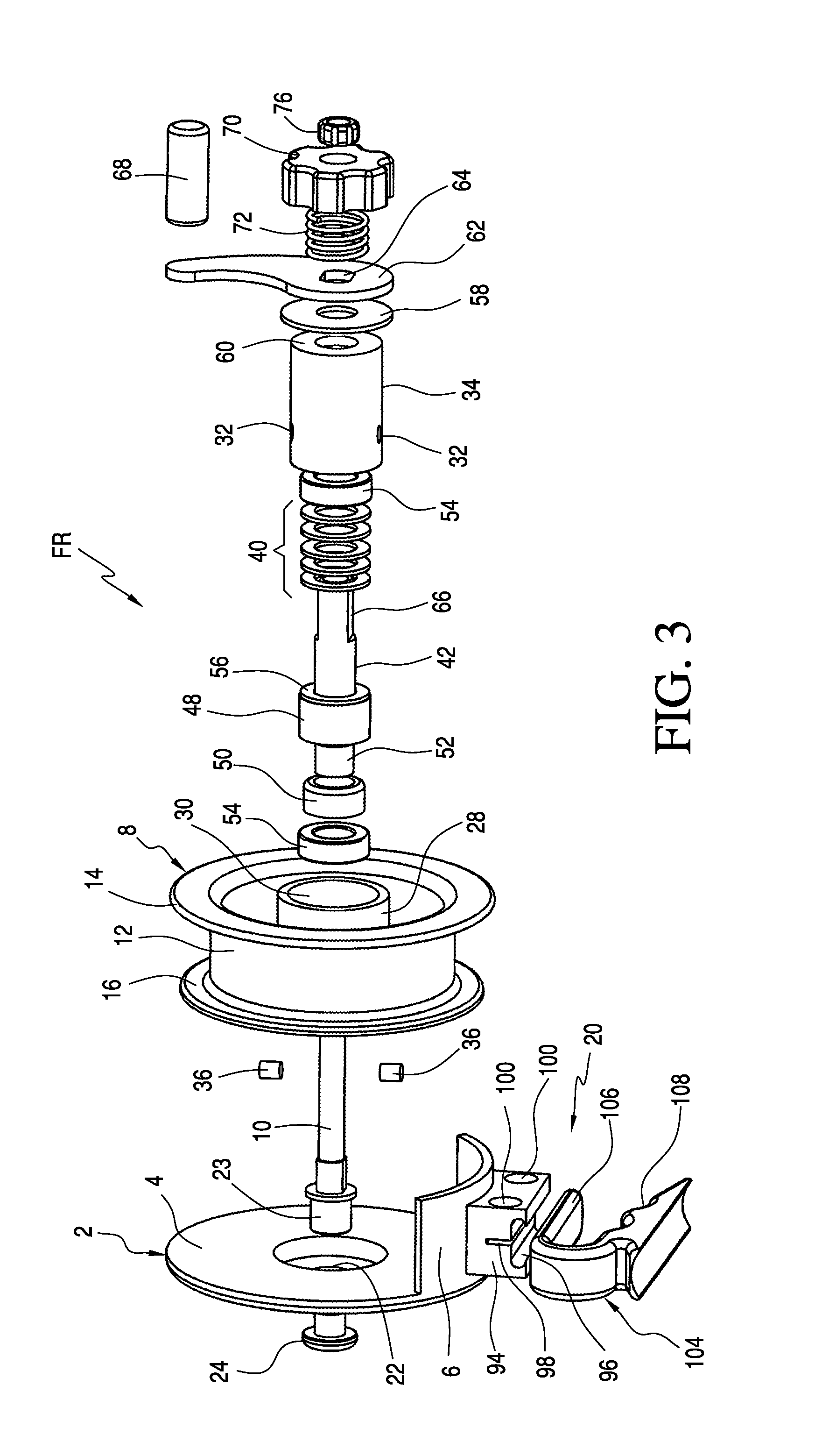
[0015]Turning to FIGS. 1 through 4, a fly reel FR according to one embodiment of the invention is shown and comprises a reel spool 8 rotatably supported on a spindle 10 secured at one end to a housing 2.

[0016]Reel housing 2 having a circumferential back plate or side wall 4 and flange portion 6 that extends transverse from side wall 4 and to which is mounted a foot assembly 20 for adjustably securing reel FR to a fly rod (not shown).

[0017]Spool 8 comprises a tubular portion 12 having radially extending side walls 14, 16 that cooperate to provide a channel around which a fly line (not shown) may be stored. The depth and width of the storage channel is variable. In the embodiment shown in FIG. 4, side wall 14 has a diameter greater than side wall 16 but generally equal to the diameter of reel housing side wall 4. Spool 8 is provided with a centrally disposed spool hub 28 having an interior race surface 30. Hub 28 is provided with a pair of locking recesses 30 that extend though the hu...


PUM


Abstract

A fly reel comprises a housing having a back plate, a spindle extending from the back plate, a spool rotatably mounted on the spindle, an adjustable drag assembly fixed to the spool and rotatably mounted with the spool, the adjustable drag assembly is adapted to provide controlled friction against the spool during rotation of the spool, a crank member for rotating the spool in a first direction, and a one way clutch operatively associated with the spindle for permitting rotation of the crank member in the first direction only whereby the spool is adapted to rotate independent of the crank in a second direction that is opposite the first direction. In addition, the drag adjustment knob of the reel is disposed on the same side as the reel crank handle and the drag components may be sealed within a cartridge.

Description

FIELD OF THE INVENTION[0001]This invention relates to fishing reels and in particular, a fly fishing reel having a drag assembly and removable spool.BACKGROUND OF THE INVENTION[0002]A fly fishing reel will provide several functions. First and foremost it stores the fly line on the reel spool. It will also enable the user to rewind a deployed fly line back onto the spool. A fly fishing reel will often be provided with a drag mechanism that allows the user to make adjustment for forces applied to the fly line and leader. Reel drag permits slippage of the reel spool relative to the reel shaft and crank (or handle) when, for example, a fish applies a force in excess of the strength of the leader. A drag mechanism should allow for quick adjustment since forces applied to the line can arise suddenly and vary greatly depending upon several factors, such as the weight of the fish that is pulling on the line.[0003]Prior art fly reels typically position the drag control knob on the reel side ...

Claims


Application Information

Patent Timeline
Patent Type & Authority Applications(United States)
IPC IPC(8): A01K89/033
CPCA01K89/033A01K89/016
Inventor HEADER, GREGORY A.MILLER, GREGORY E.WIEST, TIMOTHY
Owner HEADER GREGORY A
Why Eureka
Try Eureka