Visibility silhouettes for masked spherical integration

a technology of masked spherical integration and silhouettes, applied in the field of 3d geometry rendering techniques, can solve the problems of leaving artifacts in rendered scenes, not geometric in nature,

Active Publication Date: 2014-06-05
DISNEY ENTERPRISES INC
View PDF0 Cites 5 Cited by
  • Summary
  • Abstract
  • Description
  • Claims
  • Application Information

AI Technical Summary

Benefits of technology

[0006]Other embodiments include a computer-readable medium that includes instructions that enable a processing unit to implement on

Problems solved by technology

Determining the visibility function is often a bottleneck in three-dimensional (3D) rendering when it is necessary to integrate visibility-masked

Method used


Image

  • Visibility silhouettes for masked spherical integration
  • Visibility silhouettes for masked spherical integration
  • Visibility silhouettes for masked spherical integration

Examples


Embodiment Construction

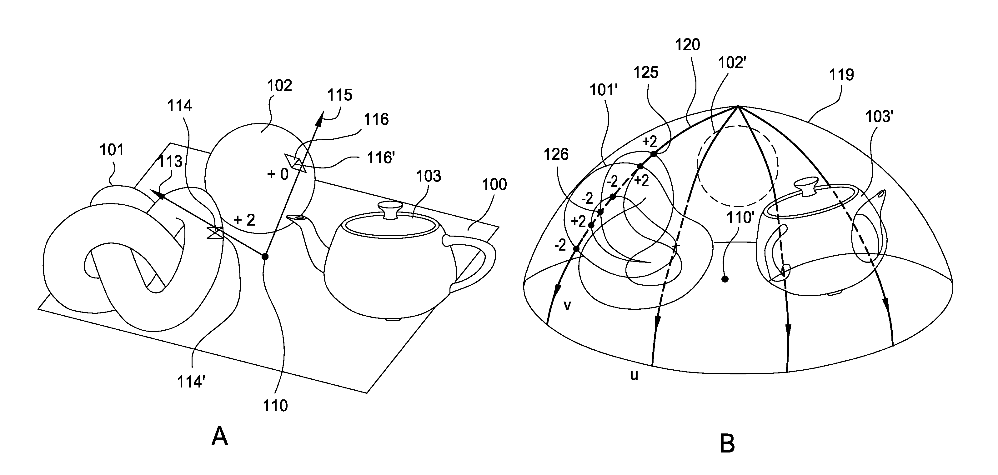
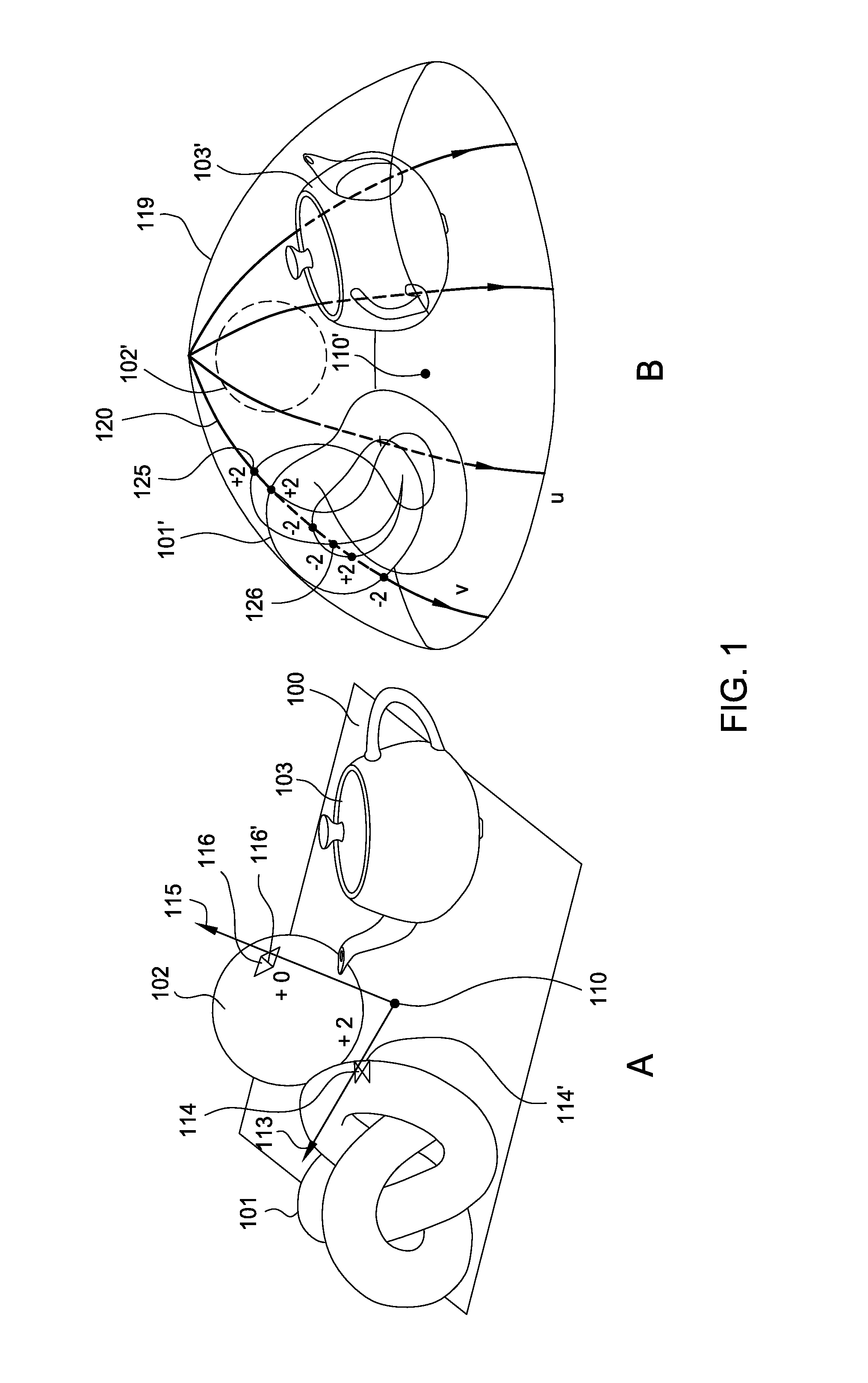
[0013]Embodiments disclosed herein provide techniques for determining, when rendering 3D geometry, integrals of visibility-masked spherical functions using visibility silhouettes. In particular, the integrals of the visibility-masked spherical functions are converted to integrals over the visibility silhouettes. For a given shade point, the visibility silhouette for that shade point includes a set of edges from the scene geometry which form the boundaries between visible and occluded regions of a hemisphere having the shade point as its center. That is, a visibility silhouette traces the boundary of the union of the objects in the scene.

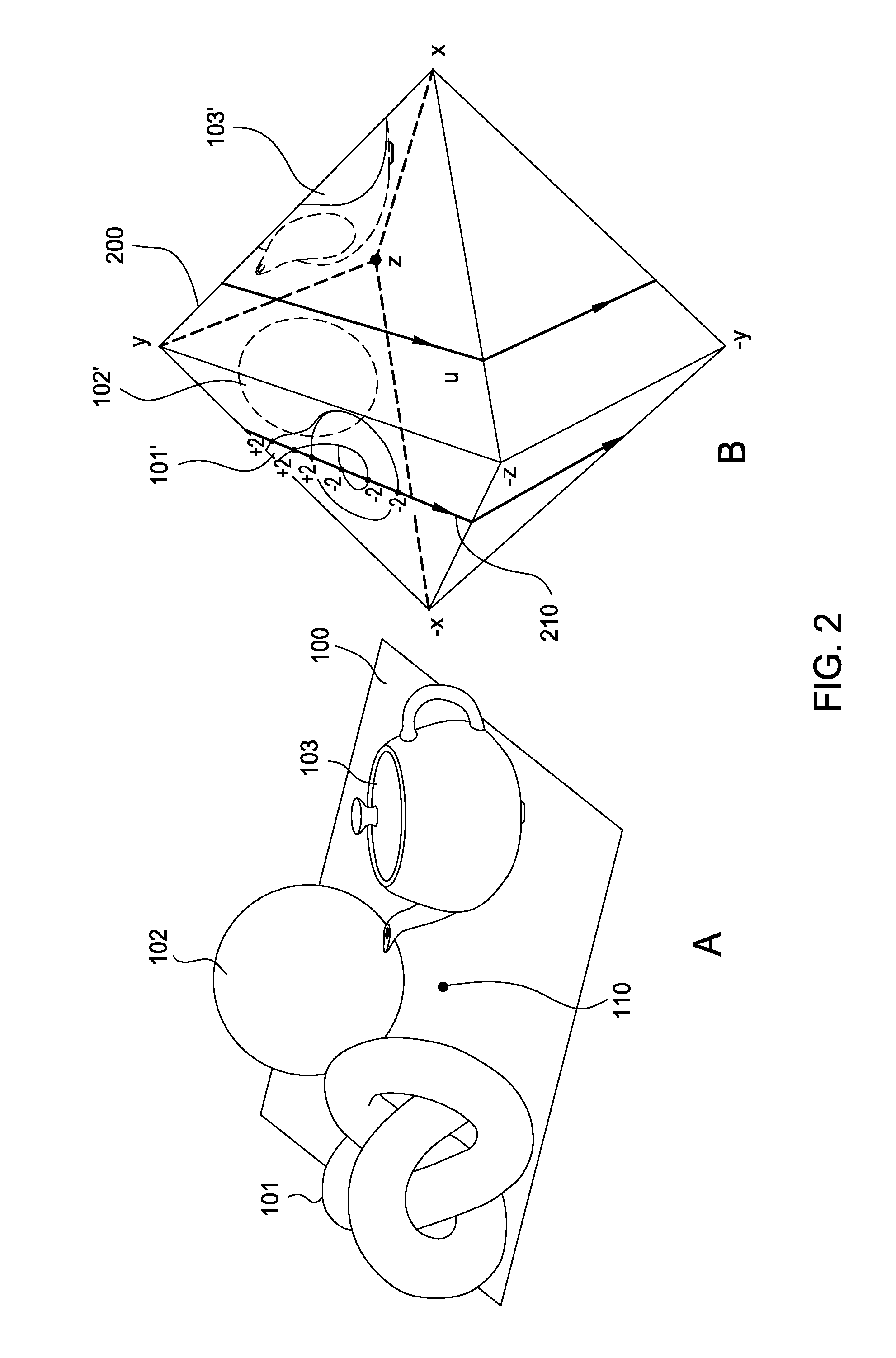
[0014]In one embodiment, a rendering application determines contour edges, discussed in greater detail below, of scene geometry for each shade point by querying a 4D dual mesh. The contour edges are a set of locally defined edges which include edges of a visibility silhouette. The rendering application may determine the integral of the visibility-mas...


PUM


Abstract

The disclosure provides an approach for determining, in 3D rendering, the integrals of visibility-masked spherical functions using visibility silhouettes. For a given shade point, the visibility silhouette for that shade point includes a set of edges from the scene geometry which form the boundaries between visible and invisible regions of a hemisphere having the shade point as its center. For each shade point, a rendering application determines a set of contour edges of scene geometry, the contour edges being a superset of the set of visibility silhouette edges, by querying a 4D dual mesh. The rendering application then evaluates the integral of the visibility-masked spherical function for a given shade point by integrating over segments of discrete u-isolines for which an overlap function indicates that a ray from the shade point would not intersect scene geometry.

Description

BACKGROUND[0001]1. Field[0002]Embodiments presented herein provide techniques for rendering 3D geometry and, in particular, using visibility silhouettes to determine integrals of visibility-masked spherical functions.[0003]2. Description of the Related Art[0004]A spherical visibility function encodes occlusion from surrounding geometry at each point of a scene. Determining the visibility function is often a bottleneck in three-dimensional (3D) rendering when it is necessary to integrate visibility-masked spherical functions. Typically, the visibility function is determined via sampling, such as ray tracing or hardware shadow mapping. However, such approaches are not geometric in nature. Further sampling approaches can leave artifacts in the rendered scenes.SUMMARY[0005]One embodiment of the invention includes a computer implemented method which includes receiving geometry of a scene, and, for each of a plurality of shade points in the scene, determining a visibility silhouette havin...

Claims


Application Information

Patent Timeline
IPC IPC(8): G06T15/80
CPCG06T15/80G06T15/06G06T15/40
Inventor NOWROUZEZAHRAI, DEREKBARAN, ILYAMITCHELL, KENNYJAROSZ, WOJCIECH
Owner DISNEY ENTERPRISES INC
Why Eureka
Try Eureka