Electronic card connector and electronic device using the same

a technology of electronic devices and card connectors, applied in the direction of coupling device connections, instruments, computing, etc., can solve the problem that the need for electronic devices including a new card connector is still presen

Inactive Publication Date: 2014-06-05
SCIENBIZIP CONSULTINGSHENZHENCO
View PDF5 Cites 23 Cited by
  • Summary
  • Abstract
  • Description
  • Claims
  • Application Information

AI Technical Summary

Problems solved by technology

However, an electronic device including a new card connector is still needed.

Method used


Image

  • Electronic card connector and electronic device using the same
  • Electronic card connector and electronic device using the same
  • Electronic card connector and electronic device using the same

Examples


Embodiment Construction

[0012]Embodiments of the present disclosure will be described with reference to the accompanying drawings.

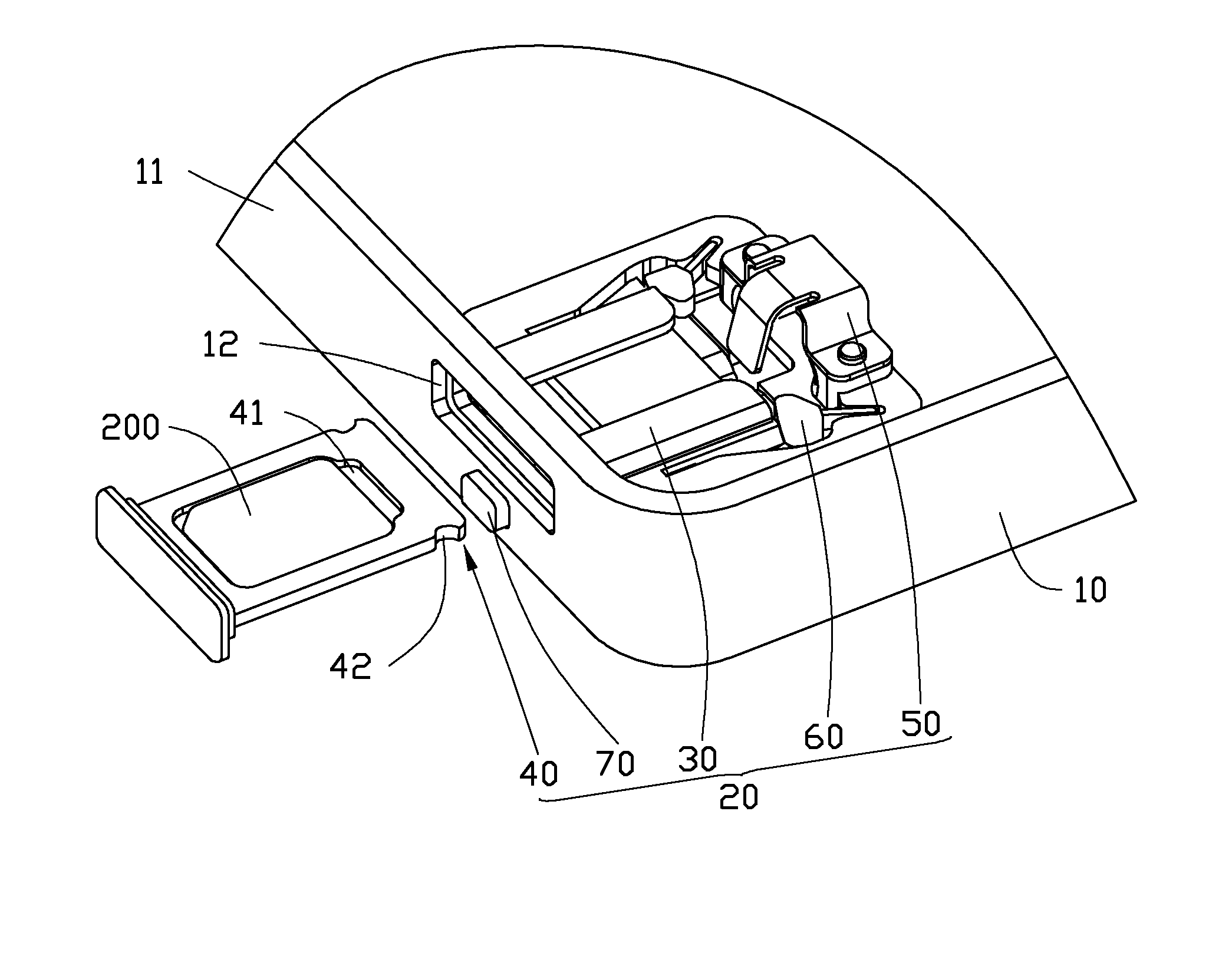
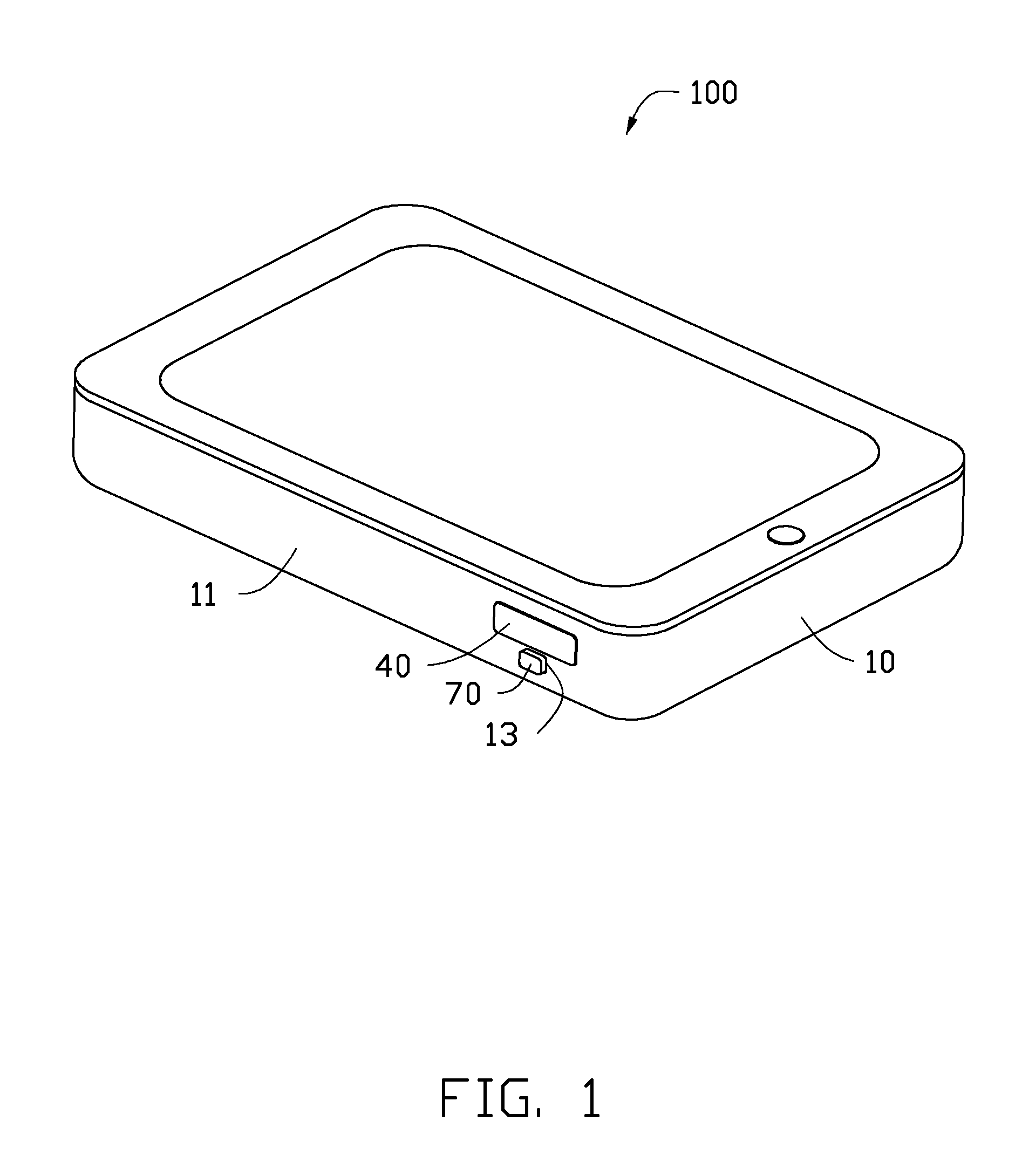
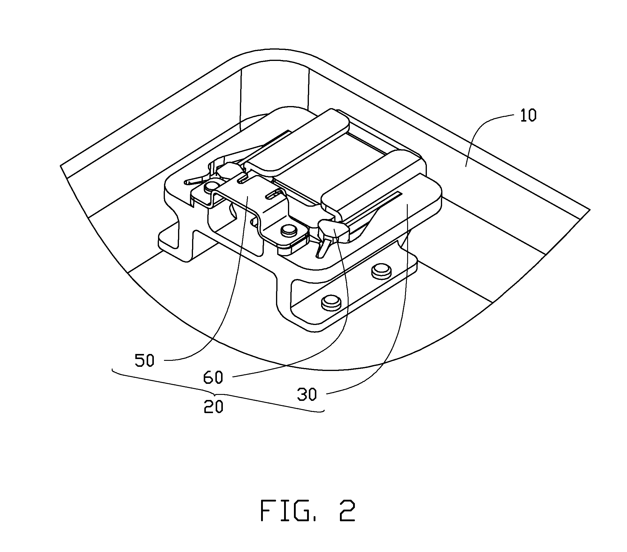
[0013]Referring to FIGS. 1-3, an electronic device 100 includes housing 10 and an electronic card connector 20 that is used to adapt an electronic card 200, such as a flash memory card or a subscriber identity module (SIM) card. The electronic card connector 20 includes a main body 30 secured within the housing 10, and a tray 40 slidably connected to the main body 30. The tray 40 defines a recess 41 to receive the electronic card 200, and can be inserted into the housing 10 through a slot 12 defined in a sidewall 11 of the housing 10.

[0014]Referring to FIGS. 4-5, the connector 20 further includes an elastic ejection member 50, a locking member 60, and a pushing member 70. A first, top side 31 of the main body 30 includes a guiding member 32 and defines a through hole 33. The guiding member 32 is used to guide the tray 40 to slide along a first direction (indicated by arrow A of ...


PUM


Abstract

An electronic card connector for adapting an electronic card is provided. The electronic card connector includes a locking member having a block. The block can be received in a notch of a tray accommodating an electronic card, thereby holding the electronic card in position. The electronic card connector further includes a elastic ejection member to eject the tray out when the block disengages from the notch of the tray. The tray moves in a first direction, and the block moves in a second direction that is substantially perpendicular to the first direction.

Description

BACKGROUND[0001]1. Technical Field[0002]The present disclosure relates to an electronic card connector.[0003]2. Description of Related Art[0004]Many portable electronic devices such as cell phones and tablet computers include a card connector for adapting an electronic card, such as a flash memory card. Many types of electronic card connectors have been proposed. However, an electronic device including a new card connector is still needed.BRIEF DESCRIPTION OF THE DRAWINGS[0005]Many aspects of the embodiments can be better understood with reference to the following drawings. The components in the drawings are not necessarily drawn to scale, the emphasis instead being placed upon clearly illustrating the principles of the present disclosure. Moreover, in the drawings, like reference numerals designate corresponding parts throughout the several views.[0006]FIG. 1 is an isometric view of an electronic device according to one embodiment.[0007]FIG. 2 a partial view of the electronic devic...

Claims


Application Information

Patent Timeline
Patent Type & Authority Applications(United States)
IPC IPC(8): H01R12/70
CPCH01R12/7058H01R2201/06G06K13/0806G06K13/085G06K7/04
Inventor CAO, YAN-BANG
Owner SCIENBIZIP CONSULTINGSHENZHENCO
Why Eureka
Try Eureka