Vehicular camera system

a camera system and vehicle technology, applied in the field of vehicles, can solve the problems of requiring space within the vehicle, obstructing the driver's field of view,

Active Publication Date: 2014-06-12
MAGNA ELECTRONICS
View PDF10 Cites 225 Cited by
  • Summary
  • Abstract
  • Description
  • Claims
  • Application Information

AI Technical Summary

Problems solved by technology

However, front-facing vehicular camera systems may obstruct a driver's field of view and may require space within the vehicle beyond what can readily be provided.

Method used


Image

  • Vehicular camera system
  • Vehicular camera system
  • Vehicular camera system

Examples


Embodiment Construction

[0021]A vehicular camera system can be installed on the inside of the front windshield of a vehicle, such as a car, truck, bus, or van. Such a camera system may be used for a variety of functions such as object detection, lane keeping, and high beam control.

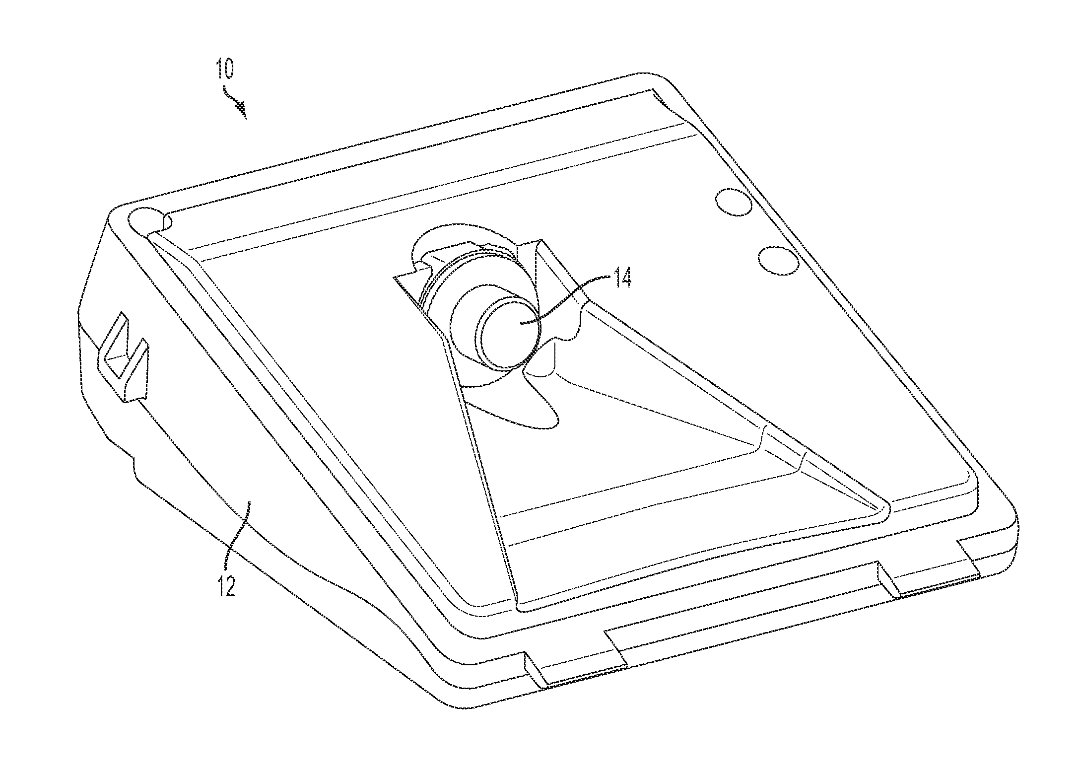
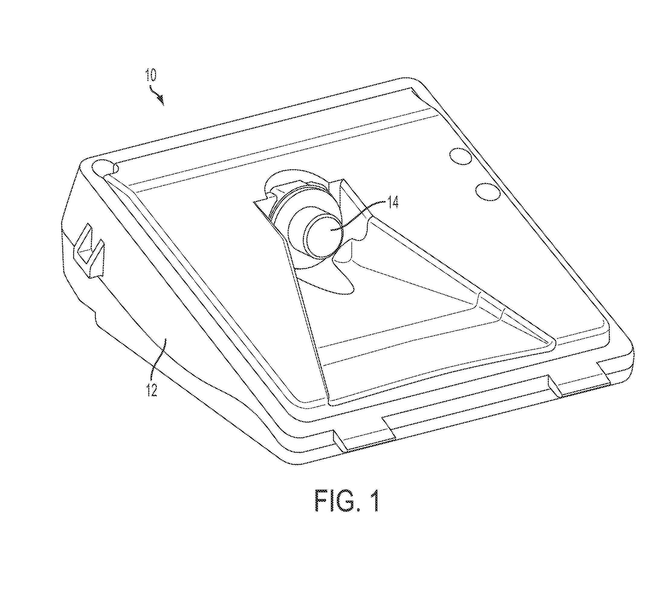
[0022]FIG. 1 shows an example of a vehicular camera system or module 10 configured to be attached in a front-facing manner to a vehicle. The camera system 10 includes a housing 12 and a lens barrel 14 projecting therefrom.

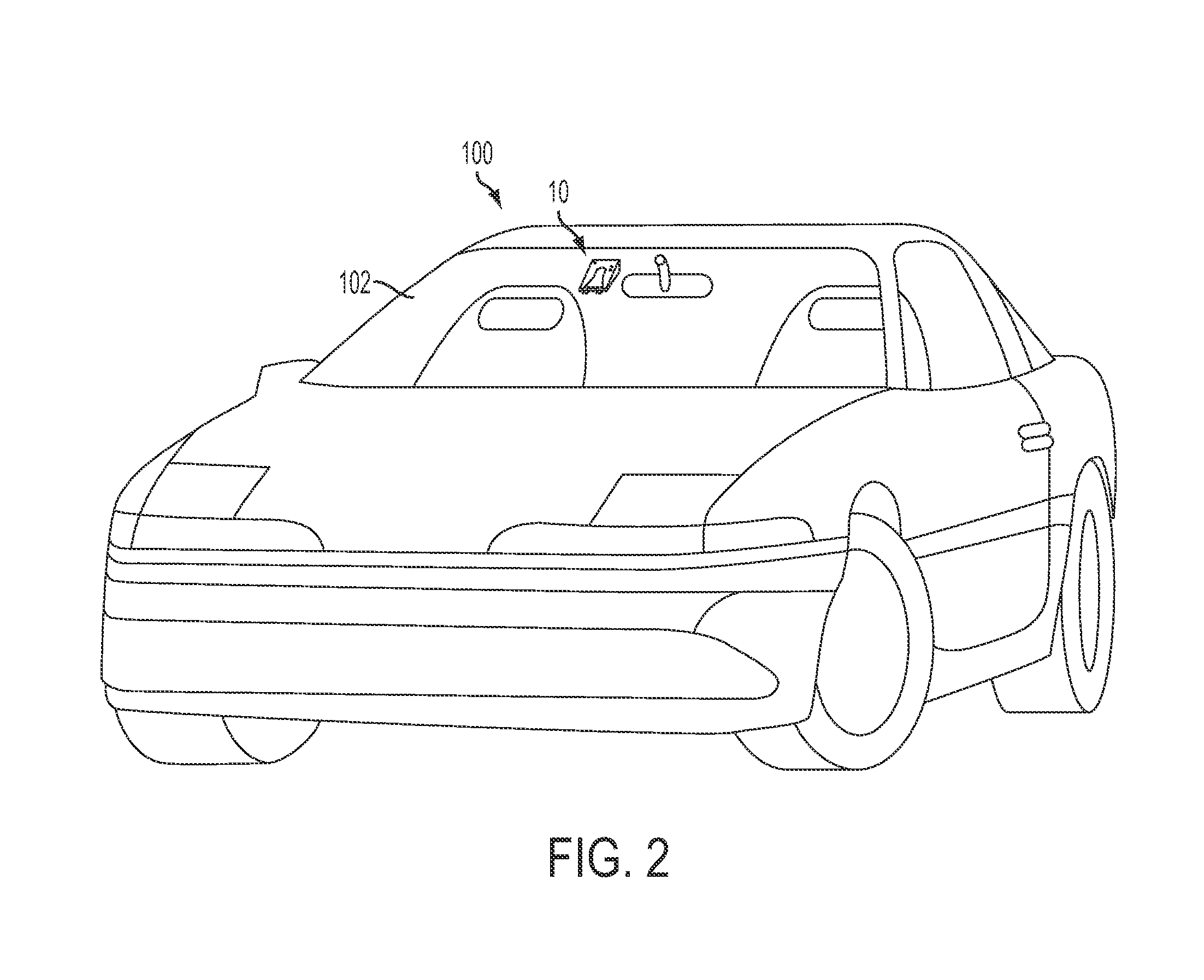
[0023]FIG. 2 shows a forward-facing position for a camera system 10 in the vehicle 100. The camera system or module 10 can be attached to the windshield 102, as shown, such as via a frame or bracket that is adhesively attached at the windshield via a plurality of fixing elements or attachment elements. Other positions are also possible. The camera system or camera module of the present invention may utilize aspects of the systems and / or modules described in U.S. Pat. Nos. 7,916,009; 7,888,629; 7,728,721; 7,533,9...


PUM

PropertyMeasurementUnit
heightaaaaaaaaaa
heightaaaaaaaaaa
lengthaaaaaaaaaa

Abstract

A vehicular camera system includes an imager assembly that can include an imager disposed on an imager circuit board and a lens positioned to direct light to the imager. A main circuit board is operatively connected to the imager circuit board. The main circuit board can include at least one processor for processing images captured by the imager. The main circuit board has an opening, and at least a portion of the imager assembly extends through the opening.

Description

CROSS REFERENCE TO RELATED APPLICATIONS[0001]The present application claims the filing benefit of U.S. provisional applications, Ser. No. 61 / 583,431, filed Jan. 5, 2012, and Ser. No. 61 / 514,191, filed Aug. 2, 2011, which are hereby incorporated herein by reference in their entireties.FIELD OF THE INVENTION[0002]This disclosure relates to vehicles, and more particularly, to a vehicular camera system.BACKGROUND OF THE INVENTION[0003]Vehicular camera systems can provide vehicle operators with valuable information about driving conditions. For example, a typical vehicle camera system can aid a driver in parking her automobile by alerting her to hazards around her automobile that should be avoided. Other uses for vehicle camera system are also known.[0004]However, front-facing vehicular camera systems may obstruct a driver's field of view and may require space within the vehicle beyond what can readily be provided.SUMMARY OF THE INVENTION[0005]According to one aspect of this disclosure, ...

Claims


Application Information

Patent Timeline
Patent Type & Authority Applications(United States)
IPC IPC(8): H04N5/225
CPCY10T29/49169B60K2370/21B60K2370/152B60K2370/173B60K2370/777H04N23/52H04N23/57H04N23/55H04N23/51H04N23/54B60R1/00B60R1/04B60R1/12B60R11/04B60R2001/1215B60R2001/1253B60R2011/0026B60R2300/102B60R2300/105B60R2300/303B60R2300/607B60R2300/8026B60R2300/804B60R2300/806
Inventor ACHENBACH, GARRETTWINDEN, BRIAN J.VAN DAN ELZEN, CHRISTOPHER L.
Owner MAGNA ELECTRONICS
Why Eureka
Try Eureka