Connector

Inactive Publication Date: 2014-06-19
YAZAKI CORP
View PDF0 Cites 7 Cited by
  • Summary
  • Abstract
  • Description
  • Claims
  • Application Information

AI Technical Summary

Benefits of technology

[0036]Therefore, even when a slit or the like is not provided, engagement between the projection portion for provisionally retaining and the provisionally retaining portion or between the projection portion for completely retaining and the completely retaining portion can be completed without applying an excessive load to the parts to be mutually engaged between the attachmen

Problems solved by technology

Therefore, if an excessive load is applied to them in the event of engagement, the engaged portions may be crushed or broken, i.e., the engaged portions may be damaged.
However, in a countermeasure in which the slit 126 is provided on a wall portion of the

Method used


Image

  • Connector
  • Connector
  • Connector

Examples


Example

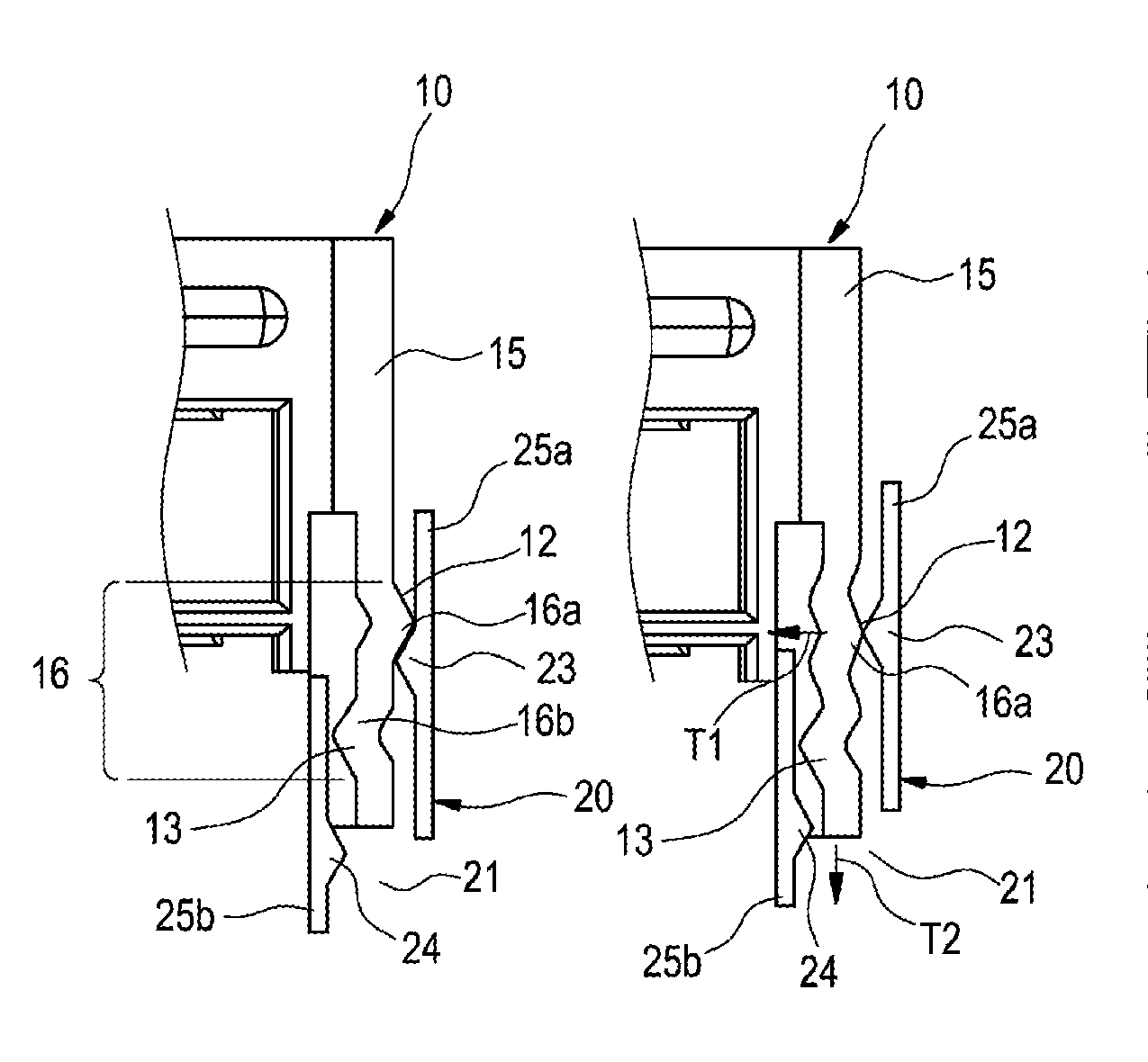
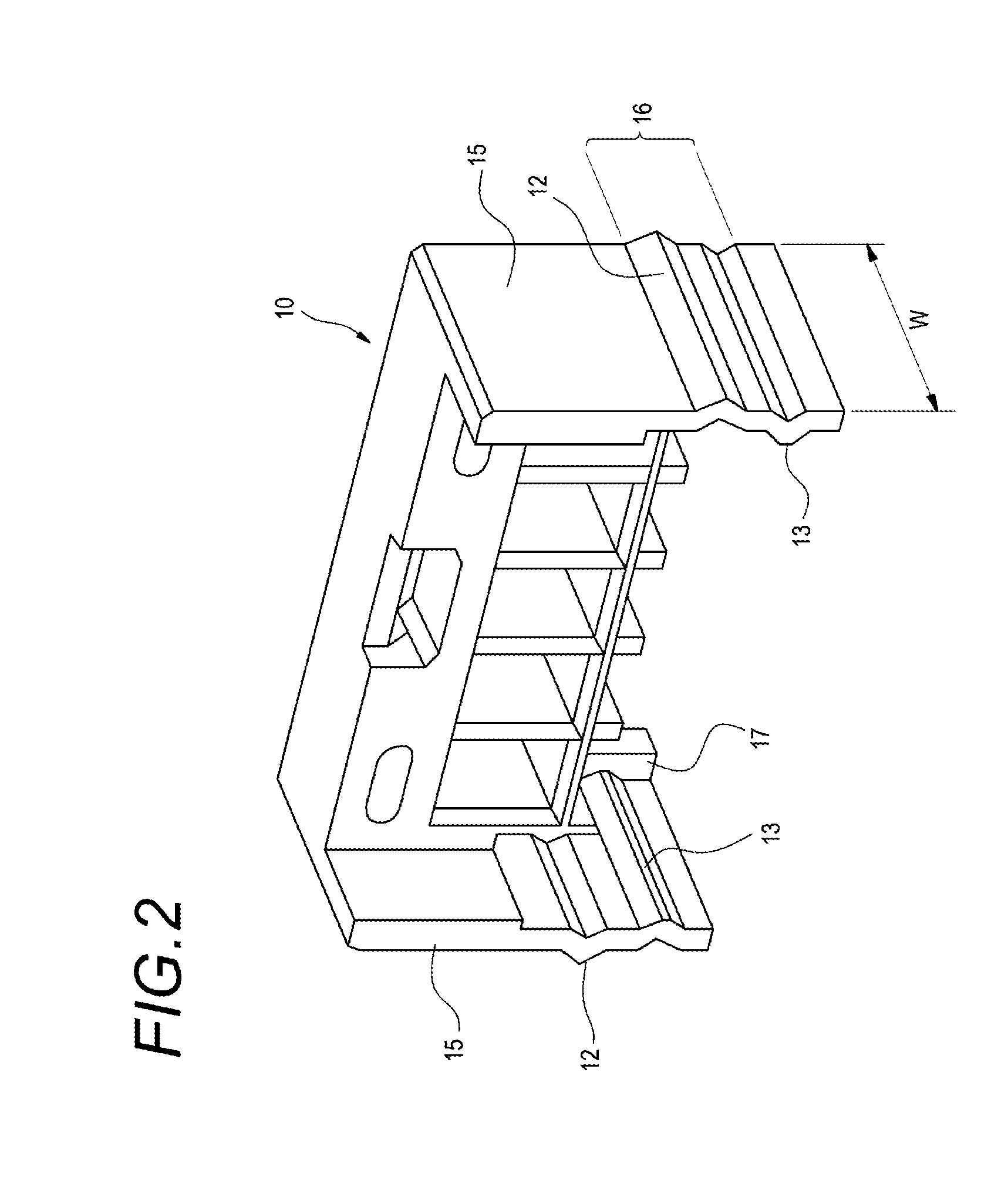
[0060]In the case of the retaining structure of an attachment component in the first embodiment as described above, the projection portion 12 for provisionally retaining and the projection portion 13 for completely retaining provided on the spacer 10, are the wave shaped projection portions 16a and 16b on each of the wave shaped plate sections 16 which are respectively formed on the pair of outer side walls 15 extending along the insertion direction of the spacer 10. The projection portion 12 for provisionally retaining or the projection portion 13 for completely retaining functions as a plate spring that elastically deforms in a flat shape by the pressure load that the projection portion 16a or 16b receives when it is brought into contact with the provisionally retaining portion 23 or the completely retaining portion 24 at the housing body 20 side.

[0061]Therefore, even in a case where a slit or the like is not provided, it is possible to complete engagement between the projection p...

Example

[0068]A basic structure of the spacer 10A of the second embodiment can be the same as that of the spacer 10 of the first embodiment, and the elements or members the same as in the first embodiment are denoted by the same numerals, and their descriptions are omitted.

[0069]A point at which the spacer 10A of the second embodiment is different from the spacer 10 of the first embodiment, is an end face 161 of the projection portion 16a on the wave shaped plate section 16 to be engaged with the provisionally retaining portion 23 of the housing body 20 and an end face 162 of the projection portion 16b on the wave shaped plate section 16 to be engaged with the completely retaining portion 24 are made to be flat faces perpendicular to the insertion direction. Also, the provisionally retaining portion 23 and the completely retaining portion 24 respectively have end faces perpendicular to the insertion direction so as to be engaged with the end faces 161, 162 of the projection portions 16a, 16...


PUM


Abstract

A connector includes a housing body and an attachment component that is inserted in a component containing space of the housing body. The attachment component has a side wall extending in an insertion direction of the attachment component into the component containing space. The housing body includes a provisionally retaining portion and a completely retaining portion. The attachment component has a first projection portion which is retained to the provisionally retaining portion at a provisionally retaining position. The attachment component has a second projection portion which is retained to the completely retaining portion at a completely retaining position. The side wall includes a wave shaped plate section having elasticity, and the wave shaped plate section has the first and second projection portions which are formed in a shape of a wave progressing along the insertion direction.

Description

CROSS REFERENCE TO RELATED APPLICATIONS[0001]This application is a continuation of PCT application No. PCT / JP2012 / 071931, which was filed on Aug. 23, 2012 based on Japanese Patent Application (No. 2011-181774) filed on Aug. 23, 2011, the contents of which are incorporated herein by reference.BACKGROUND OF THE INVENTION[0002]1. Field of the Invention[0003]The present invention relates to a connector with an attachment component, especially, a retaining structure of the attachment component in the connector in which an attachment component inserted into a component containing space of a housing body of the connector is positioned on one of two positions of a provisionally retaining position and a completely retaining position.[0004]2. Description of the Related Art[0005]FIG. 6 is a schematic view illustrating a retaining structure of an attachment component in a connector disclosed in JP-A-64-54678 as described below.[0006]A connector 100 shown in FIG. 6 is provided with a spacer 110 ...

Claims


Application Information

Patent Timeline
IPC IPC(8): H01R13/436F16B17/00
CPCF16B17/00H01R13/436H01R13/4362Y10T403/7064
Inventor NISHIYAMA, NORITAKA
Owner YAZAKI CORP
Why Eureka
Try Eureka