Connector and manufacturing method therefor

a manufacturing method and connector technology, applied in the field of connectors, can solve the problems of complex structure of the lower mold for insert molding, lid needs to be covered with resin, cannot be supported by the upper mold, etc., to achieve simple structure, high accuracy, and not complicated mold structure

Active Publication Date: 2020-11-05
SUMITOMO WIRING SYST LTD
View PDF0 Cites 6 Cited by
  • Summary
  • Abstract
  • Description
  • Claims
  • Application Information

AI Technical Summary

Benefits of technology

[0016]Accordingly, the nut can be pressed against the mold via the core resin portion by injecting the resin material for constituting the outer resin portion toward the opposite side surface of the core resin portion from the gate. Further, if the core resin portion is formed with a through hole as described later, the nut can be pressed directly against the mold, utilizing the through hole by the injection of the resin material. Thus, no clearance is formed between the mold and the nut, utilizing a pressure during the injection of the resin material. In this way, the nut is maintained in the targeted specified posture in the connector manufactured by molding the outer resin portion.
[0017]Further, the nut is positioned by a shape changed portion, such as a projection, formed in the mold when molding the outer resin portion. This shape changed portion for positioning the nut need not be a movable portion capable of moving with respect to the mold through rotation, a sliding movement or the like, and is formed by changing the shape of the mold. In this way, the structure of the mold is not complicated.
[0018]Therefore, the connector of the first aspect can be molded by the mold having a simple structure, and can be molded with the position and posture of the nut maintained with high accuracy.
[0019]The connector manufacturing method of the second aspect is a method suitable for manufacturing the connector of the first aspect. According to this connector manufacturing method, the connector can be molded with the position and posture of the nut maintained with high accuracy by the mold having a simple structure.

Problems solved by technology

Thus, the structure of the lower mold for insert molding becomes complicated.
Further, in Japanese Unexamined Patent Publication No. 2017-105150, the lid needs to be covered with resin and cannot be supported by the upper mold.
Further, in, U.S. Pat. No. 7,189,920 the nut needs to be covered with resin, and therefore cannot be supported by the upper mold.

Method used


Image

  • Connector and manufacturing method therefor
  • Connector and manufacturing method therefor
  • Connector and manufacturing method therefor

Examples


first embodiment

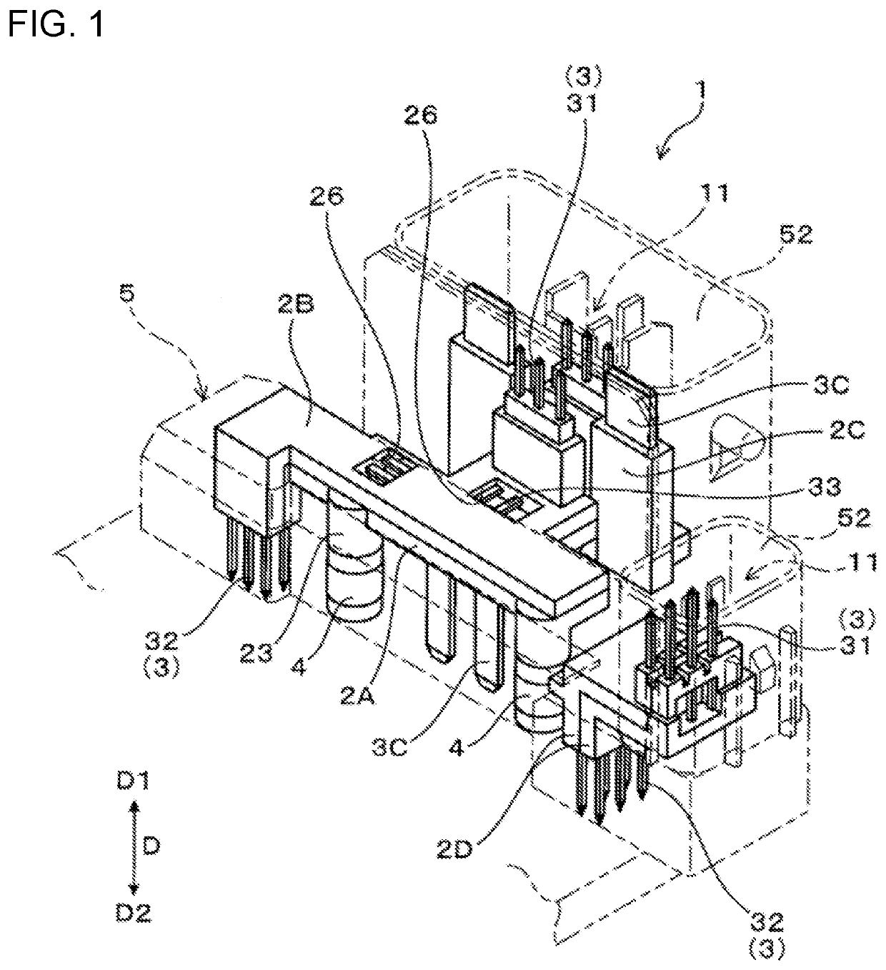
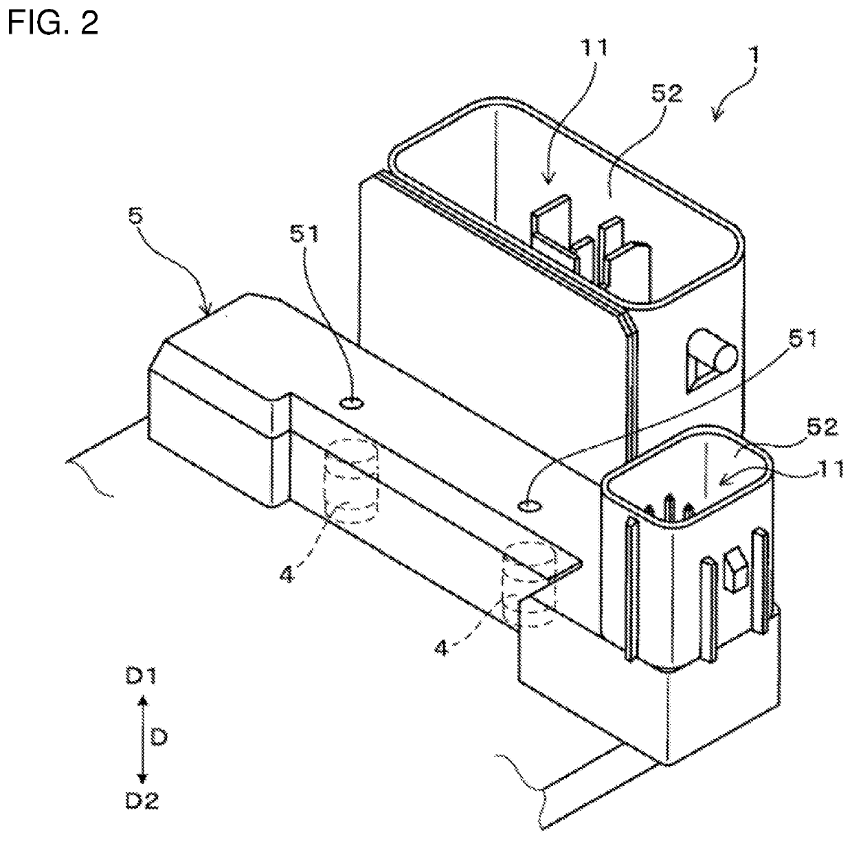
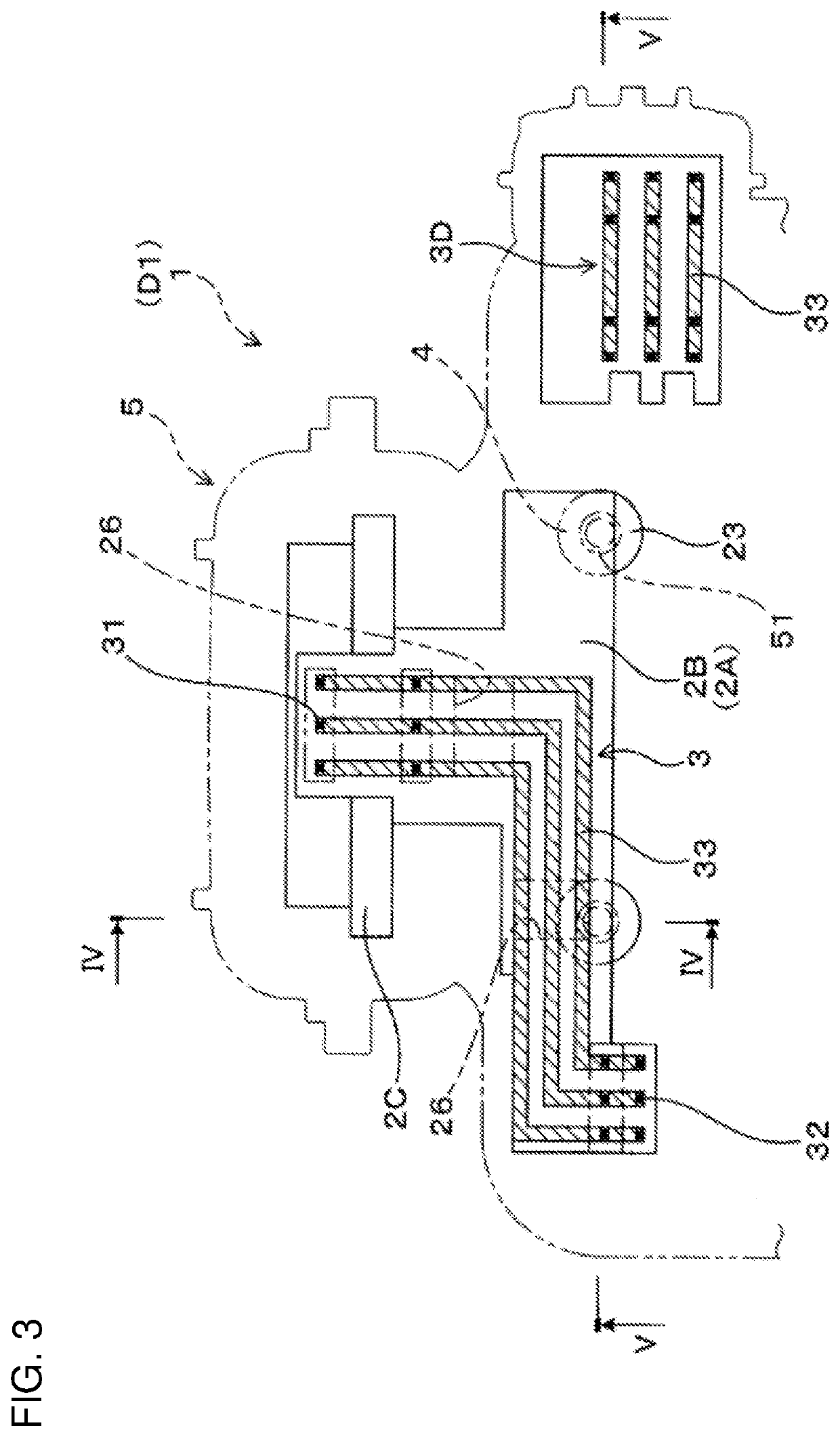
[0037]A connector 1 of this embodiment includes connector terminals 3, core resin portions 2A, 2B, nuts 4 and an outer resin portion 5, as shown in FIGS. 1 to 5. The connector terminals 3 are conductive conductors. Both end parts 31, 32 of the connector terminals 3 project from the core resin portions 2A, 2B, and intermediate parts 33 of the connector terminals 3 (except the both end parts 31, 32) are embedded in the core resin portions 2A, 2B.

[0038]As shown in FIGS. 1, 4 and 5, the nuts 4 are arranged to face a nut facing surface 21A of the core resin portion 2A. Each nut 4 includes a screw hole 40 extending from an outer end surface 41 located on a side opposite to a side facing the nut facing surface 21A. The outer resin portion 5 covers the core resin portions 2A, 2B and the nuts 4 with exposed surfaces 25 as parts of the core resin portions 2A, 2B and the outer end surfaces 41 of the nuts 4 exposed. Injection marks 51 made during the molding of the outer resin portion 5 are for...

second embodiment

[0090]In a connector 1 of this embodiment, through holes 27 to be filled by an outer resin portion 5 are formed in a first core resin portion 2A and a second core resin portion 2B as shown in FIGS. 13 and 14 to more reliably maintain nuts 4 in specified postures.

[0091]As shown in FIGS. 13 and 14, the through holes 27 penetrating toward the nuts 4 are formed in parts of the first and second core resin portions 2A, 2B of this embodiment facing the nuts 4. The through holes 27 of the first core resin portion 2A penetrate from nut facing surfaces 21A of facing projections 23 to an opposite side surface 22A. The through holes 27 of the second core resin portion 2B penetrate at positions facing the through holes 27 of the first core resin portion 2A.

[0092]The outer resin portion 5 is filled continuously into the through holes 27 of the first core resin portion 2A and those of the second core resin portion 2B. Further, injection marks 51 of this embodiment are formed on a surface of a part...


PUM

PropertyMeasurementUnit
pressureaaaaaaaaaa
structureaaaaaaaaaa
timeaaaaaaaaaa

Abstract

A connector (1) includes a plurality of connector terminals (3), core resin portions (2A), (2B), nuts (4) and an outer resin portion (5). A plurality of the nuts (4) are arranged to face a nut facing surface (21A) of the core resin portion (2A). The outer resin portion (5) covers the core resin portions (2A), (2B) and the nuts (4) with exposed surfaces (25) of the core resin portions (2A), (2B) and outer end surfaces (41) of the nuts (4) exposed. Injection marks (51) during molding of the outer resin portion (5) are formed on a surface of a part of the outer resin portion (5) covering an opposite side surface (22B) located on a side opposite to the nut facing surface (21A).

Description

BACKGROUNDField of the Invention[0001]The invention relates to a connector including a plurality of connector terminals and a manufacturing method therefor.Related Art[0002]A connector provided with connector terminals is used in wiring an electronic control component and a control device in various machine components. The connector terminals may be arranged in a connector case made of resin by performing insert molding. Further, a nut for mounting the connector on various mounting components may be arranged in the connector case by performing insert molding.[0003]Japanese Unexamined Patent Publication No. 2017-105150 discloses an insert molded article and a manufacturing method where a through nut and a lid are covered by insert molding of resin so that a first opening of the through nut is closed by the lid and a second opening of the through nut is exposed to outside. In performing the insert molding, an inner peripheral side of the second opening of the through nut is fit to a p...

Claims


Application Information

Patent Timeline
Patent Type & Authority Applications(United States)
IPC IPC(8): H01R13/504B29C45/14B29C45/27
CPCB29C45/2708H01R13/504B29L2031/36B29C45/14065H01R13/405H01R31/06H01R43/24H01R2201/26B29C45/14639B29C45/0025B29C2045/0027
Inventor YAMADA, HIROKI
Owner SUMITOMO WIRING SYST LTD
Why Eureka
Try Eureka