

X-shaped support structure device
A technology for supporting structures and connecting rods, applied in electrical components, electrical switches, circuits, etc., can solve the problems of poor strength and rigidity of small cylinders, inconvenient cleaning of pollutants, breakage and damage, etc. The effect of improving quality and service life
- Summary
- Abstract
- Description
- Claims
- Application Information
AI Technical Summary
Problems solved by technology
Method used
Image

Examples
Embodiment 1
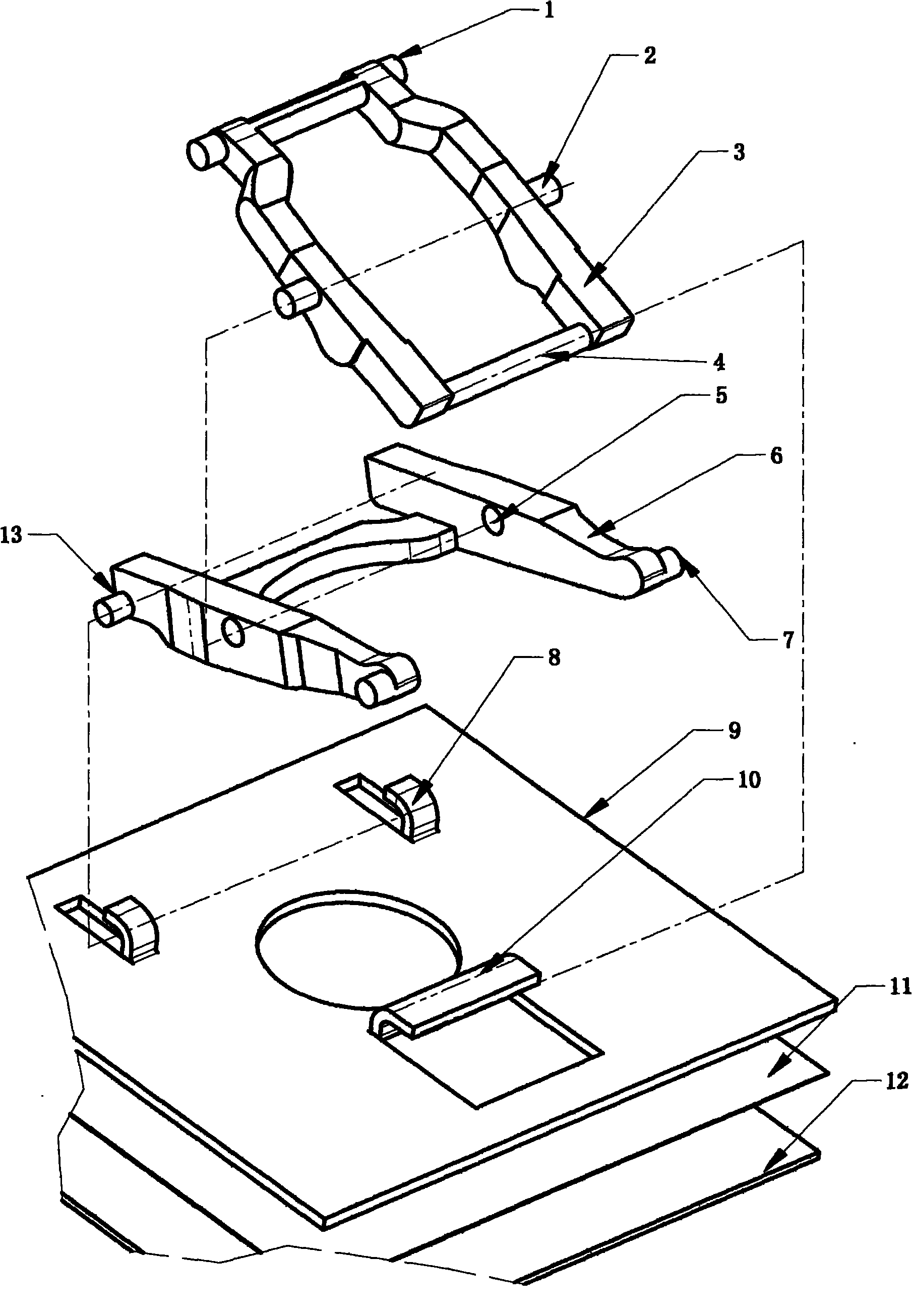
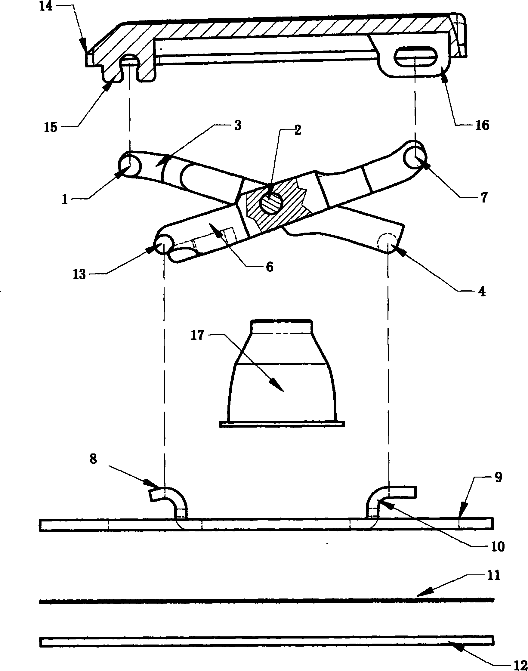
[0033] see image 3 , Figure 4 The X supporting structure device of the present invention is made of the keycap 14 that has keycap rotating part 15 and keycap sliding part 16, rubber elastic ring 17, has the support plate 9 of rotating part 8 and sliding part 10, membrane switch piece 11, base plate 12 And be positioned at keycap 14 by the X support that inner frame connecting rod 3, outer frame connecting rod 6 rotate in the middle part.
[0034] see Figure 4 1. The pivot shaft 2 of the inner frame on the inner frame connecting rod 3 is hinged with the outer frame pivot hole 5 on the outer frame connecting rod 6, and the lower hinge shaft 13 of the outer frame and the lower shaft 4 of the inner frame are connected with the rotating part 8 on the support plate 9 respectively. And the sliding part 10 is a rotational fit and a sliding fit. The upper hinge shaft 1 of the inner frame and the upper sliding shaft 7 of the outer frame are in rotational fit and sliding fit with t...
Embodiment 2
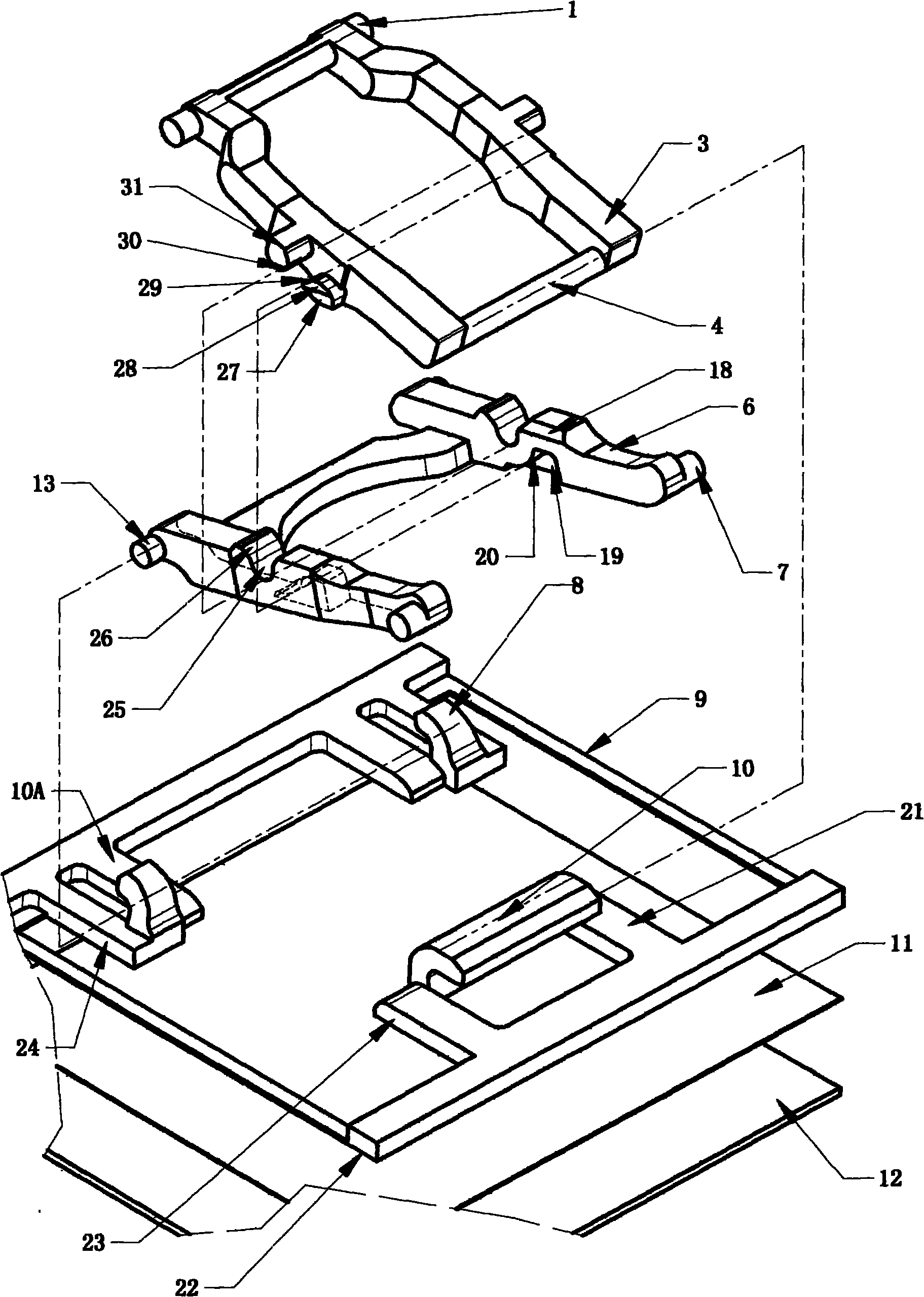
[0046] see Figure 14 , Figure 15 , Figure 16 , Figure 17 1. The sliding axis 28 is located near the upper middle of the double arms of the inner frame connecting rod 3, the rotating central axis 31 is located obliquely below the sliding central axis 28, the central groove 26 is located near the lower part of the double arms of the outer frame connecting rod 6, and the central groove 26 The opening is downward, and the central sliding groove 19 is open upward and is located near the upper part of the middle part of the double arm of the outer frame connecting rod 6 .
[0047] When the keycap 14 is pressed, the keycap 14 pushes the rubber elastic ring 17 to produce elastic deformation and move downwards, and the sliding central axis matching part 29 on the sliding central axis 28 slides downward along the sliding circular surface 20 of the central groove, and slides downwards. The central shaft matching part 29 slides the circular surface 20 along the central groove to re...
PUM
 Abstract
Description
Claims
Application Information