Exhaust diffuser and method for manufacturing an exhaust diffuser

a technology of exhaust diffuser and exhaust diffuser, which is applied in the direction of sustainable transportation, mechanical equipment, machines/engines, etc., can solve the problems of large regions of low momentum fluid generation, endanger the pressure recovery of exhaust diffuser, and less efficient exhaust diffuser, etc., to achieve enhanced pressure recovery, high range of angle of attack, and high efficiency

Active Publication Date: 2014-06-26
SIEMENS ENERGY GLOBAL GMBH & CO KG
View PDF7 Cites 7 Cited by
  • Summary
  • Abstract
  • Description
  • Claims
  • Application Information

AI Technical Summary

Benefits of technology

[0029]A second airfoil having a shape capable of handling a higher range of angle of attack may help to avoid flow separation near the inner surface of the outer member, where the flow angle may change rapidly compared to the flow angle in the middle between outer surface of the inner member and inner surface of the outer member. Hence, diffuser blockages may be avoided and pressure recovery enhanced.
[0030]According to a yet another embodiment of the exhaust diffuser for a torque-generating turbine the third airf

Problems solved by technology

The junction of the vanes of the stators of either the compressor stages or the turbine stages with the outer or inner surfaces may be sources of horseshoe vortexes and may thus impede, that the fluid flow is optimally redirected onto the rotor.
If the angle of attack becomes too high or too low flow separation may occur and large regions of low momentum fluid may be generated.
Thes

Method used


Image

  • Exhaust diffuser and method for manufacturing an exhaust diffuser
  • Exhaust diffuser and method for manufacturing an exhaust diffuser
  • Exhaust diffuser and method for manufacturing an exhaust diffuser

Examples


Embodiment Construction

[0071]The illustration in the drawing is schematically provided.

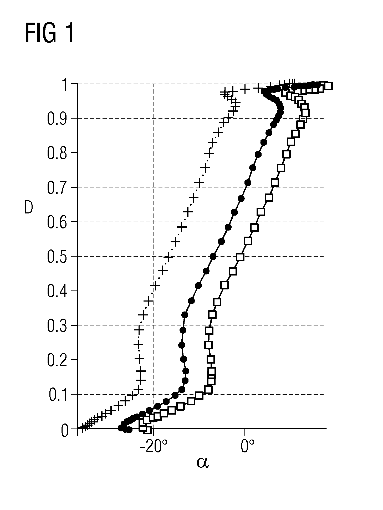
[0072]FIG. 1 shows the flow angle a of the fluid flow entering an exhaust diffuser versus the normalized distance D from the outer surface of its inner member to the inner surface of its outer member for a low, middle and high capacity of a torque-generating gas turbine. For a middle capacity the flow angle varies from −27 degree at the outer surface of the inner member of the exhaust diffuser to approximately 10 degree at the inner surface of the outer member of the exhaust diffuser. The mean flow angle is approximately 5 degree, which allows for good diffuser recovery.

[0073]In particular, near the outer surface and the inner surface the flow angle gradient is quite extreme. Accordingly, it may be advantageous to treat these end wall regions differently.

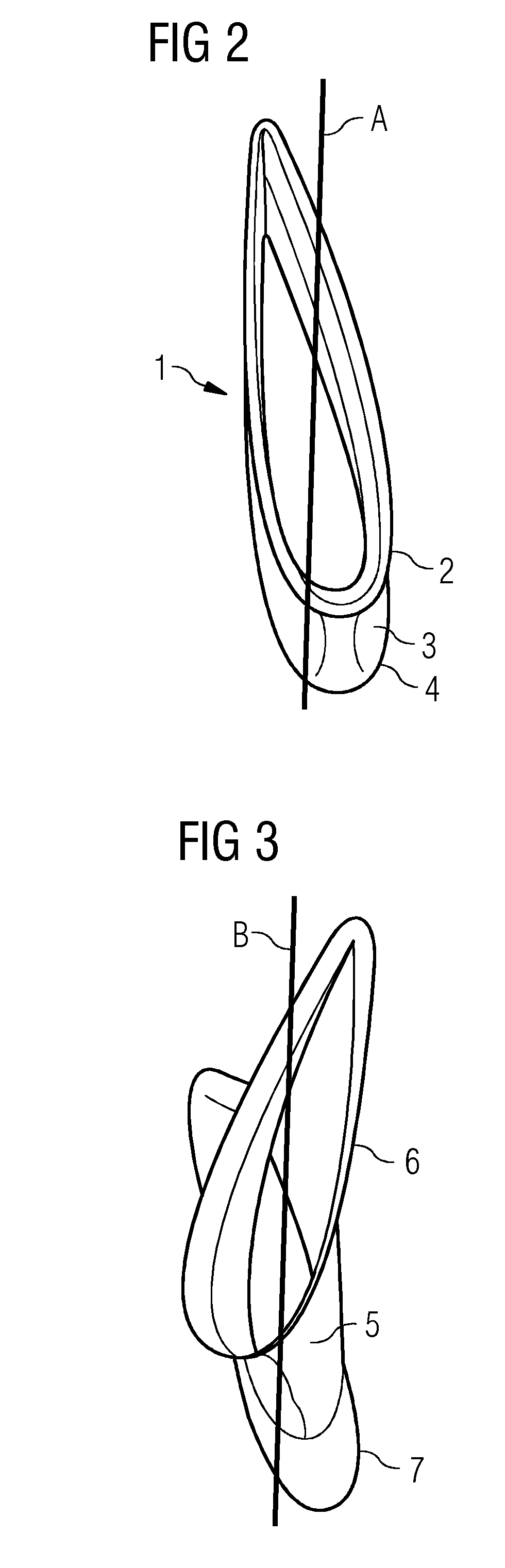
[0074]FIG. 2 shows a prismatic supporting strut 1 comprising an outer section 2, a middle section 3, and an inner section 4 the airfoils of which all have the same angl...


PUM


Abstract

An exhaust diffuser and method for manufacturing an exhaust diffuser is provided. An exhaust diffuser for a torque-generating turbine, in particular a torque-generating gas turbine is provided, the exhaust diffuser having an inner member, and the inner member having an outer surface. The outer member having an inner surface, and the inner member and the outer member forming an annular channel at least a first supporting strut connecting the inner member and the outer member, the supporting strut extending essentially radially from the inner surface to the outer surface, the supporting strut having a middle section, the middle section having a first airfoil and an outer section having a second airfoil, and the second airfoil having a higher angle of incidence than the first airfoil. Furthermore, it is described a method for manufacturing an exhaust diffuser.

Description

CROSS REFERENCE TO RELATED APPLICATIONS[0001]This application is the US National Stage of International Application No. PCT / EP2012 / 065056 filed Aug. 1, 2012, and claims the benefit thereof. The International Application claims the benefit of European Application No. EP 11178142, filed Aug. 19, 2011. All of the applications are incorporated by reference herein in their entirety.FIELD OF INVENTION[0002]The present invention relates to the field of torque-generating turbines, in particular torque-generating gas turbines. More particularly, the invention relates to an exhaust diffuser for a torque-generating turbine, in particular a torque-generating gas turbine, and a method for manufacturing an exhaust diffuser.ART BACKGROUND[0003]Torque generating turbines are rotary engines that extract energy from a fluid flow, e.g. steam flow and / or combustion gas flow, and convert it into useful work. Typically, torque-generating turbines are used to drive a generator to produce electric energy. ...

Claims


Application Information

Patent Timeline
IPC IPC(8): F01D25/30
CPCF05D2220/321F01D5/145F01D25/162F05D2240/12F01D5/146Y02T50/60F01D25/30
Inventor WONG, LI SHING
Owner SIEMENS ENERGY GLOBAL GMBH & CO KG
Why Eureka
Try Eureka