[0006] A
diffraction grating generates a
diffraction pattern which has at least one secondary maximum besides a main maximum. The
radar beam generated by the
antenna element is thus subdivided into a number of beam components which correspond to the main maximum and to the secondary maxima of the diffraction pattern. The angle between the main maximum and the first secondary maximum is a function of the
grating constant of the
diffraction grating. Thus, using a
diffraction grating having a sufficiently low grating constant, even in the case of thin lenses, into which a
prism having sufficient refractive power could hardly be integrated, a large angle between the beam components may be achieved.
[0007] The
diffraction grating may simply be placed before the lens as transmission grating or it may be developed in the flat surface of the lens, and, in this context, it may extend over the entire cross section of the lens. This has the
advantage that the lens has the same
numerical aperture for the deflected beam component corresponding to the first secondary maximum as for the main beam, so that the geometry of the deflected beam is not falsified so strongly by diffraction effects of the lens. An additional substantial
advantage, especially for the loss of
sight detection, is that the deflected beam, just as the main beam, also starts from the entire cross sectional area of the lens. Deposits of
snow, ice or
slush, that lead to a loss of
sight of the sensor, consequently have the same effect on the deflected beam component, which is used for loss of sight detection, as on the non-deflected main beam.
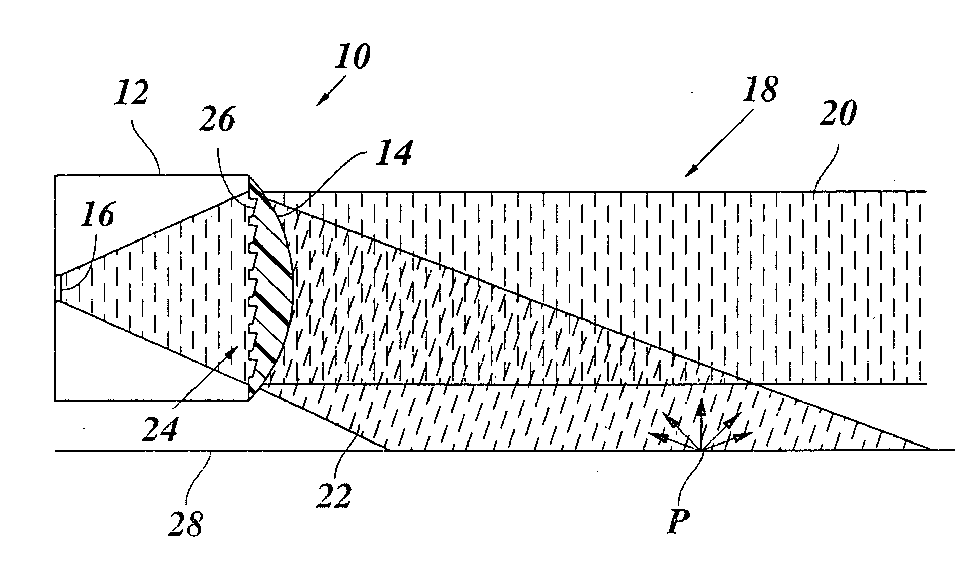
[0008] By a suitable embodiment of the diffraction grating, for example, as a so-called blaze grating, an asymmetrical diffraction pattern may be achieved, in which all secondary maxima, except for the first secondary maximum, are extensively suppressed on one side of the principal maximum, so that the beam, similar to the case of a
prism, is subdivided into only two beam components, namely a non-deflected main beam and a deflected secondary beam. Then, in the same way as with the radar sensor described in German Patent No. DE 102 07 437, the deflected beam may be directed slantwise onto the roadway surface, and used for measuring the absolute speed, for calibration control and / or for the detection of loss of sight. However, since, for the beam deflected with the aid of the diffraction grating, the entire
numerical aperture of the lens is available, this beam is easier to focus.
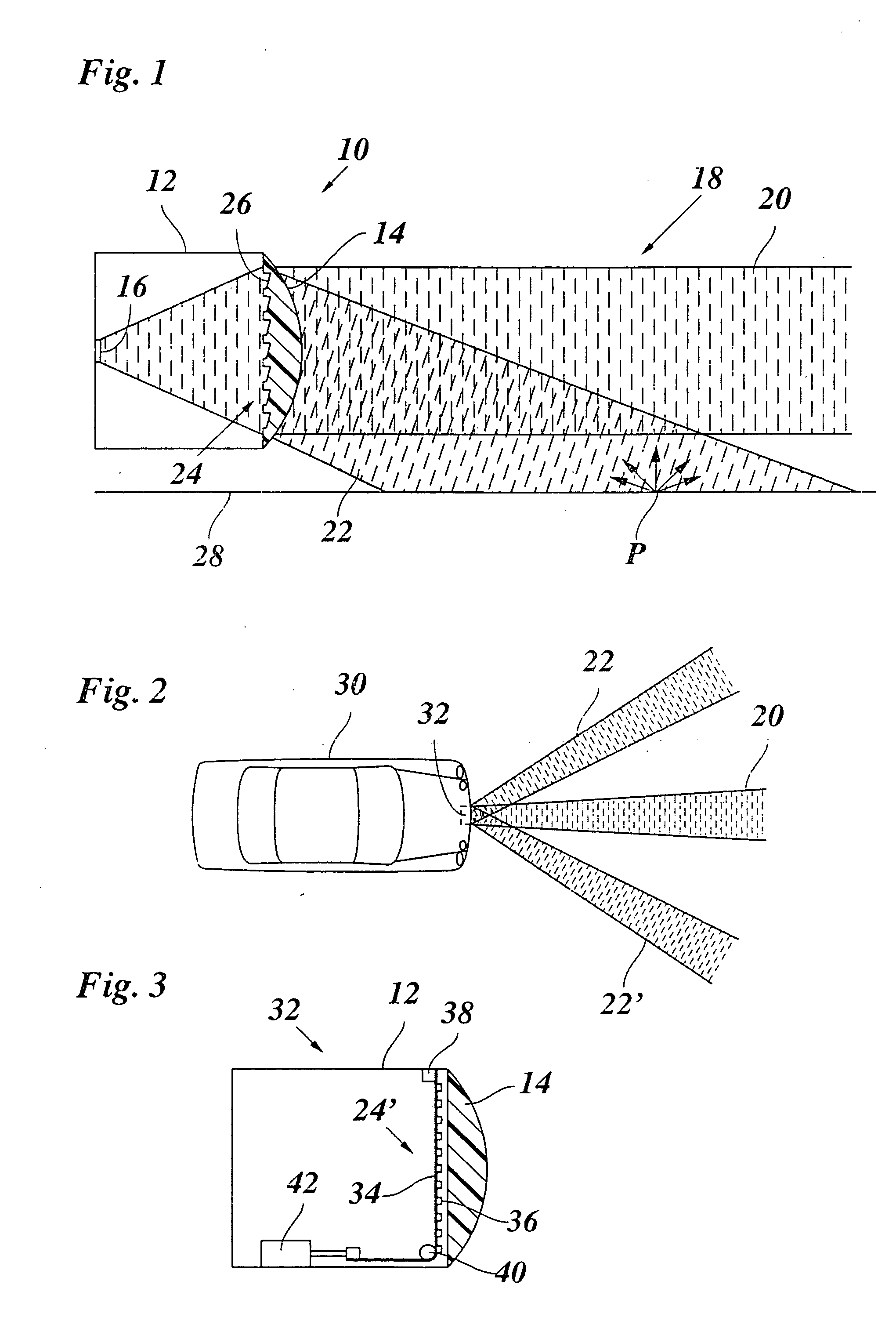
[0009] Optionally, the diffraction grating may also be oriented vertically, so that the secondary beam is deflected to the side. In this case, the secondary beam may be used, for example, for the
early detection of a driver's swinging in or for locating objects on side lanes or at the edge of the roadway. Then the diffraction grating may also be embodied in such a way that exactly two secondary beams are generated symmetrically to the main beam that correspond to the two first diffraction maxima. In this way, in the very short range of the vehicle, monitoring both side lanes or of the left side lane and the right roadway edge is made possible. By evaluating the radar echoes that are generated by the side lanes, for example, at left and right guardrails or guardrail posts, it is also possible to detect in which lane of the roadway one's own vehicle is located. A differentiation between radar echoes that are generated by the main beam on the one hand, and by secondary beams on the other hand, is, for instance, made possible in that objects that are detected by the secondary beams will have a very small distance from one's own vehicle, already at their first detection. In the case of standing objects or objects that are slower than one's own vehicle, a differentiation between echos of the left and the right secondary beam, in the case of angle-resolving radar sensors, is made possible in that the
azimuth angles of the located object change in the opposite direction.
[0010] According to one refinement of the present invention, it is also possible to vary or modulate the grating constant of the diffraction grating dynamically. This may be done, for instance, by producing the diffraction grating using electronically controllable elements, for example, using piezoelectric elements or using
photon crystal technology in a suitable substrate, so that the grating parameters are able to be controlled electronically. This also opens up the possibility of enlarging the locating angle range of the radar sensor, or to improve the
angular resolution capability, by “scanning” the environment by periodic change in the angle of deflection of the secondary beams.

